
автордың кітабын онлайн тегін оқу Motorcycle, Solo (Harley-Davidson Model WLA)
⎫
⎬
⎭
WAR DEPARTMENT Washington, 18 October 1943MOTORCYCLE, SOLO
(Harley‐Davidson Model WLA)
Dissemination of restricted matter.—The information contained in restricted documents, and the essential characteristics of restricted materiel, may be given to any person known to be in the service of the United States, and to persons of undoubted loyalty and discretion who are cooperating in Government work, but will not be communicated to the public or to the press except by authorized military public relations agencies. (See also paragraph 18b, AR 380–5, 28 September 1942.)
CONTENTS
PART ONE—VEHICLE OPERATING INSTRUCTIONS Paragraphs Pages SectionI
Introduction
1–2
3–6
II
Description and tabulated data
3–4
7–8
III
Controls and operation
5–13
9–19
IV
First echelon, preventive maintenance services
14–18
20–29
V
Lubrication
19–20
30–34
VI
Tools and equipment stowage on the vehicle
21–23
35–38
PART TWO—ORGANIZATIONAL MAINTENANCE SectionVII
Maintenance allocation
24–25
39–44
VIII
Second echelon preventive maintenance services
26
45–59
IX
Organization tools and equipment
27
60X
Trouble shooting
28–38
61–71
XI
Engine
39–44
72–77
XII
Engine—removal and installation
45–46
78–84
XIII
Clutch
47–52
85–95
XIV
Transmission
53–58
96–104
XV
Chains and sprockets
59–66
105–114
XVI
Fuel system
67–74
115–121
XVII
Intake and exhaust system
75–81
122–128
XVIII
Ignition system
82–89
129–141
XIX
Generating system
90–95
142–148
XX
Brake system
96–97
149–153
XXI
Steering control
98–101
154–166
XXII
Sheet metal and equipment
102–111
167–180
XXIII
Battery, lighting system, horn
112–118
181–190
XXIV
Instrument panel
119–121
191–192
XXV
Tires, wheels, and hubs
122–127
193–199
References 200 Index 2011 For supersession of quartermaster manuals, refer to paragraph 2.
1 For supersession of quartermaster manuals, refer to paragraph 2.
1TM 9–879
PART ONE—OPERATING INSTRUCTIONS
Section I
INTRODUCTION
Paragraph Scope
1Supersession of quartermaster manuals
21. SCOPE.
a. This technical manual2 is published for the information and guidance of the using arm personnel charged with the operation, maintenance, and minor repair of this materiel.
b. In addition to a description of the Harley‐Davidson motorcycle, this manual contains technical information required for the identification, use, and care of the materiel. The manual is divided into two parts. Part One, section I through section VI, gives vehicle operating instructions. Part Two, section VII through section XXV, gives vehicle maintenance instructions to using arm personnel charged with the responsibility of doing maintenance work within their jurisdiction.
c. In all cases where the nature of the repair, modifications, or adjustment is beyond the scope or facilities of the unit, the responsible ordnance service should be informed so that trained personnel with suitable tools and equipment may be provided, or proper instructions issued.
2. SUPERSESSION OF QUARTERMASTER MANUALS.
a. This technical manual, together with TM 9–1879, supersedes and replaces the following Quartermaster Corps publications:
(1) TM 10–1175—Maintenance manual, motorcycle, solo, Harley‐Davidson (Model 42–WLA), 11 September 1941.
(2) TM 10–1177—Maintenance manual, motorcycle, solo, Harley‐Davidson (Models 1940–41–42), 11 September 1941.
(3) TM 10–1331—Maintenance manual, motorcycle, chain drive Harley‐Davidson (Model 42 WLA, solo).
(4) TM 10–1359—Instruction folder (45–A) motorcycles, solo, Harley‐Davidson (Model 1941 WLA 45), 25 November 1941.
(5) TM 10–1361—Instruction folder (45–B) motorcycle, solo, Harley‐Davidson (Model 1941 WLA 45), 25 November 1941.
RA PD 315708
Figure 1—Top View of Motorcycle
RA PD 315709
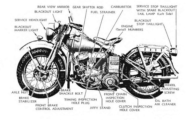
Figure 2—Left Side View of Motorcycle
RA PD 315710
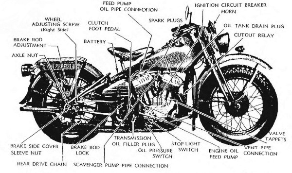
Figure 3—Right Side View of Motorcycle
2 To provide operating instructions with the materiel, this technical manual has been published in advance of complete technical review. Any errors or omissions will be corrected by changes or, if extensive, by an early revision.
1. SCOPE.
2. SUPERSESSION OF QUARTERMASTER MANUALS.
2 To provide operating instructions with the materiel, this technical manual has been published in advance of complete technical review. Any errors or omissions will be corrected by changes or, if extensive, by an early revision.
a. This technical manual2 is published for the information and guidance of the using arm personnel charged with the operation, maintenance, and minor repair of this materiel.
Section II
DESCRIPTION AND TABULATED DATA
Paragraph Description
3Data
43. DESCRIPTION (figs. 1, 2, and 3).
a. This 2‐cylinder solo motorcycle is powered by a V‐type, air‐cooled gasoline engine, operating on conventional 4‐stroke, 4‐cycle principles. Air‐cooled engines rely upon movement of air over cylinder and head radiating fins, and upon circulation of oil for dissipation of excessive heat. Motorcycle engines, therefore, under no conditions should be operated for more than 1 minute when motorcycle is not in motion.
4. DATA.
a. Vehicle Specifications.
Type of engine
2‐cylinder, V‐type L‐head, air‐cooled
Cylinder bore
2¾ in.
Stroke
3
13⁄
16in.
Engine number (serial) left side engine base, below front cylinder.
Wheelbase
4 ft 11½ in.
Length over‐all
7 ft 4 in.
Width over‐all (handle bars)
3 ft 5 in.
Wheel size
18 in.
Tire size
4.00 × 18 in.
Tire type
Drop center
Weight of vehicle (without rider or armament)
540 lb.
Ground clearance (skid plate)
4 in.
Kind and grade of fuel
Gasoline: 72 octane or higher
High gear ratio
4.59:1
Engine sprocket
31‐tooth
Countershaft sprocket
17‐tooth
Rear wheel sprocket
41‐tooth
b. Performance.
Maximum allowable speed
65 mph
Miles per gallon (hard surface)
35
Cruising range (without refill)
100 miles
Fording depth (carburetor)
18 in.
c. Capacities.
Fuel capacity (left tank)
3
3⁄
8U.S. gal
Oil tank capacity (right tank)
1
1⁄
8U.S. gal
Transmission capacity
¾ pt
3. DESCRIPTION (figs. 1, 2, and 3).
4. DATA.
RA PD 315708
Figure 1—Top View of Motorcycle
RA PD 315709
Figure 2—Left Side View of Motorcycle
RA PD 315710
Figure 3—Right Side View of Motorcycle
Section III
CONTROLS AND OPERATION
Paragraph Controls
5Engine prestarting instructions
6Starting the engine
7Stopping the engine
8Operation of vehicle
9Driving precautions
10Stopping and parking vehicle
11Towing vehicle to start engine
12Running‐in new engine (or vehicle)
13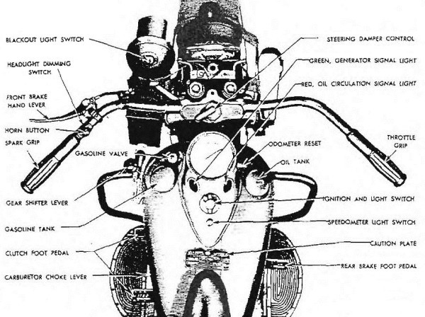
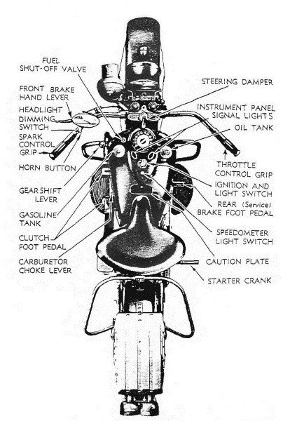
RA PD 310201
Figure 4—Controls
5. CONTROLS (fig. 4).
a. Controls are peculiar to the motorcycle. The rider must become thoroughly familiar with the location and use of all control devices before attempting to operate vehicle.
b. Gasoline Valve (figs. 5 and 6). Gasoline valve is located in left tank, forward. Valve is closed by turning to the right, finger tight. Turning to left opens valve. Valve is in normal operating position when turned to left, with valve head down. Lifting valve head releases emergency supply of fuel (3 quarts).
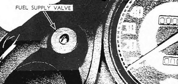
RA PD 310202
Figure 5—Fuel Supply Valve
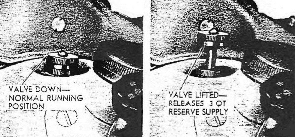
RA PD 310293
Figure 6—Fuel Supply Valve Positions
c. Throttle. The throttle is controlled by right handle bar grip. Turning grip inward opens throttle, turning it outward closes throttle.
d. Spark. Spark is controlled by left handle bar grip. Turning grip inward advances spark, turning it outward retards spark.
e. Clutch (fig. 7). Clutch is operated by left foot (rocker‐type) pedal, connecting with steel cable, which actuates clutch release lever. Pedal is located on left side of motorcycle above footboard. Forward downward (toe) position of pedal engages clutch. Rear downward (heel) position of pedal disengages clutch. Foot pedal provided with friction device to retain it in either engaged or disengaged position.
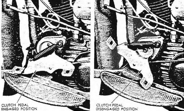
RA PD 310204
Figure 7—Clutch Pedal Positions
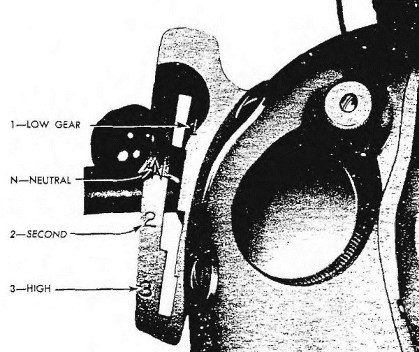
RA PD 310205
Figure 8—Gear Shifter Lever Positions
f. Service Brake (Rear Wheel). Foot pedal is located on right side of motorcycle at forward end of footboard.
g. Auxiliary Brake (Front Wheel). Auxiliary brake is operated by hand lever located on left handle bar. It is used in conjunction with service brake, as an emergency brake, or for holding vehicle while starting engine on grade. CAUTION: Brake is to be applied lightly and cautiously on wet and slippery roads.
h. Gear Shifter (fig. 8). Shifter lever is located on left tank, forward position, and operates within a guide. Shifter lever guide is notched for positive location of gears and each position is identified, front to rear: “1”—low gear; “N”—neutral; “2”—second gear; “3”—direct high gear.
RA PD 310206
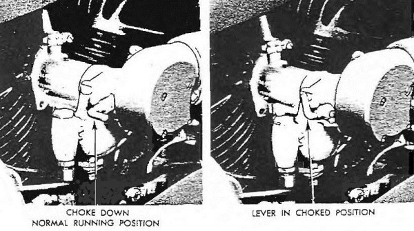
Figure 9—Carburetor Choke Lever Positions
i. Steering Damper. Steering damper is an adjustable friction device to damper turning action of forks, steady front wheel, and prevent wobble in rough terrain or at high speeds, and is located on top of steering head in center of handle bars. Move handle to right to apply desired friction.
j. Foot Starter Crank (fig. 1). The foot starter crank is located on right side of motorcycle. Gear shifter lever must be in neutral position, and clutch foot pedal in forward engaged position, before using foot starter crank. Starter crank normally is in upward position. Straddle motorcycle, place right foot on starter crank, and shift weight of body for forceful downward crank operation to start engine.
k. Ignition and Light Switch. Earlier models are provided with switch lock, later models are nonlocking. Switch is off in straight‐forward position. First position to right is for engine ignition only. Second position to right is for ignition and blackout lights. To use vehicle service lights, depress button to turn switch to third right position.
l. Instrument Panel Signal Lights. Instead of an ammeter and oil pressure gage, signal lights indicate generator charging, and engine oil pressure.
(1) Green light is located on left side of instrument panel. When engine is running, and light is out, it indicates generator is charging.
(2) Red light is located on right side of instrument panel. When engine is running, and light is out, it indicates engine oil is circulating.
m. Carburetor Choke (fig. 9). Choke lever is in full prime position when all the way up, and in normal running position when all the way down.
6. ENGINE PRESTARTING INSTRUCTIONS.
a. Before the engine is started, perform the Before‐operation Service outlined in paragraph 15. Special care must be taken during starting and warming‐up period to avoid unnecessary engine wear.
b. The rider must acquire correct motorcycle engine starting habits, and learn to do the job the quickest, easiest, and most dependable way. The following pointers will be helpful to the beginner as well as to a seasoned rider:
(1) Mount (straddle) motorcycle to obtain firm grip on handle bars.
(2) Leave side stand (jiffy stand) outward to support vehicle while operating foot starter crank with right foot.
(3) Engine starting will be benefited by use of front wheel, hand‐operated brake, to prevent vehicle from rolling or shifting during starting kicks. This is especially helpful if vehicle is parked on an incline or on soft, uneven surface.
c. The procedure outlined below is preparatory to starting either cold, warm, or hot engine:
(1) Place gear shifter lever in “N” (neutral) position (fig. 8).
(2) See that gasoline shut‐off valve is open (fig. 5).
(3) Engage clutch (fig. 7).
(4) Spark control (left) grip must be turned inward to fully advanced position, or nearly so.
(5) Foot starter crank may travel ½ way downward before starting engine. See that a full vigorous starter stroke is used. A vigorous kick, using a full swing (not a jab) of right leg and hip, is correct engine starting practice.
7. STARTING THE ENGINE.
a. Procedure for starting cold, warm, or hot motorcycle engines differs. Therefore, following instructions are used with paragraph 6 c to cover correct procedure in all three cases.
b. Starting Cold Engine. When vehicle has not been operated for some time, and engine is normally cold, follow progressive procedure for easiest starting.
(1) Set carburetor choke lever in full upward (closed) position.
(2) Open throttle wide by turning right grip inward as far as it will go.
(3) Prime cylinders by operating foot starter crank one or two strokes.
(4) Set carburetor choke lever in ¼ to ½ closed position for mild weather starting: ¾ closed (or leave fully choked) for extremely cold weather starting. CAUTION: It is only in extremely cold weather that engine may start best with choke fully closed, and even then it will have to be moved from this position immediately after engine is started.
(5) Set throttle (right) grip to slightly open position.
(6) Turn ignition switch on, first right position.
(7) Start engine with vigorous strokes of foot starter crank.
(8) When engine starts, set throttle for moderate idling speed for warming up, or until ready to set vehicle in motion. Do not race engine unnecessarily.
(9) After engine warms up, and misfires due to an overrich mixture, gradually move choke lever downward. After engine has thoroughly warmed up, move choke lever to fully open (downward) position.
c. Starting Warm Engine. Following instructions apply to engine when halfway between hot and cold. With engine in this condition, carburetor choking must be handled cautiously.
(1) Lift choke lever to first upward position from normal (¼ closed).
(2) Set throttle (right) grip to fully closed (outward) position.
(3) Operate foot starter crank one or two strokes.
(4) Set throttle grip to between ¼ and 1⁄3 open position.
(5) Turn ignition switch on.
(6) Start engine with vigorous strokes of foot starter crank.
(7) Soon after engine starts, choke lever must be moved to fully open (downward) position.
(8) Turn throttle grip to control idling speed of engine.
d. Starting Hot Engine. If engine has been shut off for only a brief period and is near normal operating temperature, it is not necessary to use carburetor choke lever. With some engines, depending upon carburetor condition and adjustment, hot starting is easier and more dependable if foot starter crank is operated one stroke before turning ignition switch on.
(1) Close throttle grip by turning fully outward.
(2) Turn ignition switch on.
(3) Operate foot starter crank to start engine.
(4) When hot engine does not start readily after two or three strokes of the foot starter crank, it is usually due to an overrich (flooded) condition, and the proper procedure then is to open throttle wide so that more air can enter: close throttle quickly after engine starts. CAUTION: After engine has warmed up to a normal operating temperature, do not allow engine to stand idling for longer than a 1 minute interval.
e. Starting Engine with Dead Battery. See paragraph 12.
f. Behavior of Instrument Panel Signal Lights. Function of generator (green) signal light depends upon action of cut‐out relay; engine oil pressure (red) signal light depends upon action of oil feed pump. Rider must, therefore, thoroughly understand operating characteristics of both signal lights to judge condition of generator‐battery circuit and pressure in engine oil circulating system.
(1) When ignition light switch is turned to first (right) position, preparatory to starting engine, both green and red signal lights should go on. CAUTION: When switch is turned on, immediately after engine has been primed by cranking, red (oil pressure) signal light may not light at once, but will light after a few seconds, due to oil pressure built up by cranking, and is most likely to be noticed in cold weather.
(2) With engine started and running at medium idling speed, both signal lights should go off. CAUTION: Should oil pressure (red) signal light fail to go off at speeds above idling, conditions must be brought to attention of unit mechanic.
(3) At slow idle speed, or under approximately 20 miles per hour road speed (in high gear), generator (green) signal light will normally flash on and off, because at that speed generator voltage output is very low and unsteady. CAUTION: Should generator (green) signal light fail to go off at speed above approximately 20 miles per hour, generator is either not charging at all, or its current output is not up to normal, and generator should be given attention at once.
8. STOPPING THE ENGINE.
a. Stop engine only by turning ignition and light switch to off (straight‐ahead) position, to prevent discharge of battery through spark coil primary circuit.
9. OPERATION OF VEHICLE.
a. Starting on Level Ground. The engine having been warmed up and checked for satisfactory operation, the vehicle (with operator in riding position) is put in motion as follows:
(1) Transfer body weight to right leg.
(2) Fold back side stand (jiffy stand).
(3) Disengage clutch by depressing clutch foot pedal with heel of left foot.
(4) Shift gear shifter lever into “1” (low) gear position.
(5) Slowly engage clutch by depressing clutch foot pedal with toe of left foot.
(6) When clutch starts to “take hold,” open throttle sufficiently to maintain engine speed.
(7) Accelerate gradually to between 12 and 15 miles per hour in low gear.
(8) Close throttle quickly.
(9) Disengage clutch.
(10) Shift through “N” (neutral) position into “2” (second) gear.
(11) Reengage clutch and accelerate to about 25 miles per hour.
(12) Close throttle quickly.
(13) Disengage clutch.
(14) Shift into “3” (high) gear.
(15) Reengage clutch and accelerate to desired speed.
b. Starting on Uneven or Soft Ground.
(1) If standing on an incline or in loose, heavy ground, more engine power will be required to start vehicle without stalling engine.
(2) It may be necessary to keep vehicle from rolling by keeping pressure on front brake hand lever. Brake pressure is released after vehicle starts in forward motion.
(3) Open throttle and engage clutch at same time to provide power needed for starting, without racing engine unnecessarily.
(4) Motorcycle starts should be made without excessive application of power, with consequent unnecessary spinning of rear wheel.
10. DRIVING PRECAUTIONS.
a. Practice will enable a rider to judge at what rate of speed the motorcycle should be moving before he shifts from a lower to higher gear, and engine should never be permitted to labor unduly, when a shift of gears, higher to lower, would improve operation.
(1) Operator must not look down at gear shifter when shifting gears, but keep his eyes on the road ahead. Do not ride the clutch. The operator’s foot should rest on clutch foot pedal only when he is operating it. When shifting gears, disengage clutch fully to avoid gear damage and shifting difficulties. CAUTION: Many transmissions are ruined through failure to disengage clutch fully when shifting gears.
b. Braking. Rear wheel service brake must be in such condition that medium‐hard application will cause rear wheel to lock. Application of service brake should be gradual, with just enough force to accomplish desired result.
(1) Auxiliary front wheel brake, when used in conjunction with service brake, must be applied with caution, especially on wet, muddy, or slippery roads.
(2) After passing through water, the brakes should be set slightly, and the vehicle operated for a short distance, until sufficient heat has been generated to dry the brakes.
c. Avoid Low Gear Operation. Always operate vehicle in highest gear possible, consistent with tactical situation, speed required, power required, and kind and nature of road substance, to prevent overheating of engine.
d. High Speed Tips. Only experienced riders should indulge in high‐speed riding. A motorcycle operated for long distances at high speed must be given closer than ordinary attention to avoid serious engine overheating with consequent damage. For better motorcycle service, apply the following suggestions:
(1) Develop habit of frequently snapping throttle shut for an instant when running at high speed. This draws additional lubrication to piston and cylinder and assists in cooling engine.
(2) In cool weather, operate engine slowly until it is thoroughly warmed up, to avoid damage to pistons, rings, cylinders, and other parts before oil is warm enough to circulate freely.
(3) If handle bar windshield and leg shields are used, engine is more likely to overheat with continued high‐speed riding. Watch this carefully.
(4) Adjust “steering damper” for best control of motorcycle consistent with riding speed and condition and nature of road.
11. STOPPING AND PARKING VEHICLE.
a. Stopping Vehicle. Rider will make a “restart” easier and quicker if he will apply the following instructions upon stopping vehicle:
(1) Close throttle.
(2) Disengage clutch.
(3) Apply brake (or brakes) to slow vehicle without sliding rear tire.
(4) Just before coming to a complete stop, shift into “N” (neutral) position and engage clutch. CAUTION: If immediate restart is to be made, shift into “1” (low) gear and allow clutch foot pedal to remain in disengaged position. (Rider will be mounted on motorcycle with engine running.)
(5) Continue brake application to complete stop.
(6) After vehicle slows to point where it can no longer be balanced by steering, place left foot on ground to maintain balance until right foot can be removed from brake operating pedal. CAUTION: Do not idle engine longer than 1 minute.
(7) Stop engine by turning ignition switch off.
b. Parking Vehicle.
(1) Lean motorcycle on side (jiffy) stand.
(2) Shift into “1” (low) gear.
(3) Engage clutch so vehicle cannot roll.
(4) Shut off gasoline supply by turning valve (to right) finger‐tight against its seat.
12. TOWING VEHICLE TO START ENGINE.
a. In emergencies when engine cannot be started with foot starter crank, it can be started by towing the motorcycle.
(1) Set gear shifter lever in “2” (second) gear position.
(2) Disengage clutch.
(3) Choke carburetor.
(4) Turn ignition switch on.
(5) After momentum of the towed motorcycle reaches between 10 and 15 miles per hour, engage clutch, and continue procedure until engine starts.
b. Engine Starting with Dead Battery. Emergency engine starting with dead battery can be effected by making use of freshly charged battery, or by towing as outlined above. If vehicle with dead battery is to be towed for engine starting, proceed as follows:
(1) Disconnect battery negative wire from ground on right side of motorcycle.
(2) Tow motorcycle for engine starting.
(3) After engine is started, reconnect battery ground wire to frame to prevent damage to electrical system.
13. RUNNING‐IN NEW ENGINE (OR VEHICLE).
a. A new motorcycle engine or newly overhauled engine must be given proper “break‐in” consideration for at least the first 1,000 to 1,200 miles of service. Failure to do this may result in damage that will put engine out of active service within a short period of time.
b. At the first 250 miles, check front and rear drive chains to make sure they are receiving required amount of oil for ample lubrication. If necessary, have chain oilers adjusted by unit mechanic. Drive chains must be inspected for correct adjustment, and be given attention by unit mechanic as needed.
c. At first 500 miles, drain oil tank and refill with fresh oil. Check front and rear chains (step b above). Thereafter, follow instructions in Maintenance Operation section.
d. After a new motorcycle has been run 500 to 1,000 miles it needs to be thoroughly checked over and any loose screws and nuts tightened. Particular attention must be given engine and transmission mounting bolts and nuts, and to rear wheel mounting socket screws.
e. Following pointers must be observed when running‐in new engine or newly overhauled engine:
(1) Do not exceed 30 miles per hour during first 100 miles.
(2) Do not exceed 35 miles per hour during next 200 miles.
(3) Do not exceed 40 miles per hour during next 400 miles.
(4) Do not exceed 50 miles per hour during next 500 miles.
(5) Avoid use of low gears during break‐in operation as much as possible.
5. CONTROLS (fig. 4).
6. ENGINE PRESTARTING INSTRUCTIONS.
7. STARTING THE ENGINE.
8. STOPPING THE ENGINE.
9. OPERATION OF VEHICLE.
10. DRIVING PRECAUTIONS.
11. STOPPING AND PARKING VEHICLE.
12. TOWING VEHICLE TO START ENGINE.
13. RUNNING‐IN NEW ENGINE (OR VEHICLE).
RA PD 310202
Figure 5—Fuel Supply Valve
RA PD 310293
Figure 6—Fuel Supply Valve Positions
15. BEFORE‐OPERATION SERVICE.
Section IV
FIRST ECHELON PREVENTIVE MAINTENANCE SERVICES
Paragraph Purpose
14Before‐operation service
15During‐operation service
16At‐halt service
17After‐operation and weekly service
1814. PURPOSE.
a. To insure mechanical efficiency it is necessary that the vehicle be systematically inspected at intervals each day it is operated and weekly, so that defects may be discovered and corrected before they result in serious damage or failure. Certain scheduled maintenance services will be performed at these designated intervals. The services set forth in this section are those performed by driver or crew before operation, during operation, at halt, after operation, and weekly.
b. Driver preventive maintenance services are listed on the back of “Driver’s Trip Ticket and Preventive Maintenance Service Record,” W.D. Form No. 48, to cover vehicles of all types and models. Items peculiar to specific vehicles, but not listed on W.D. Form No. 48, are covered in manual procedures under the items to which they are related. Certain items listed on the form that do not pertain to the vehicle involved are eliminated from the procedures as written into the manual. Every organization must thoroughly school each driver in performing the maintenance procedures set forth in manuals, whether or not they are listed specifically on W.D. Form No. 48.
c. The items listed on W.D. Form No. 48 that apply to this vehicle are expanded in this manual to provide specific procedures for accomplishment of the inspections and services. These services are arranged to facilitate inspection and conserve the time of the driver, and are not necessarily in the same numerical order as shown on W.D. Form No. 48. The item numbers, however, are identical with those shown on that form.
d. The general inspection of each item applies also to any supporting member or connection, and generally includes a check to see whether the item is in good condition, correctly assembled, secure, or excessively worn.
(1) The inspection for “good condition” is usually an external visual inspection to determine whether the unit is damaged beyond safe or serviceable limits. The term “good condition” is explained further by the following: not bent or twisted, not chafed or burned, not broken or cracked, not bare or frayed, not dented or collapsed, not torn or cut.
(2) The inspection of a unit to see that it is “correctly assembled” is usually an external visual inspection to see whether it is in its normal assembled position in the vehicle.
(3) The inspection of a unit to determine if it is “secure” is usually an external visual examination, a hand‐feel, or a pry‐bar check for looseness. Such an inspection should include any brackets, lock washers, lock nuts, locking wires, or cotter pins used in assembly.
(4) “Excessively worn” will be understood to mean worn close to, or beyond, serviceable limits, and likely to result in a failure if not replaced before the next scheduled inspection.
e. Any defects or unsatisfactory operating characteristics beyond the scope of first echelon to correct must be reported at the earliest opportunity to the designated individual in authority.
15. BEFORE‐OPERATION SERVICE.
a. This inspection schedule is designed primarily as a check to see that the vehicle has not been tampered with, or sabotaged since the After‐operation Service was performed. Various combat conditions may have rendered the vehicle unsafe for operation and it is the duty of the driver to determine whether or not the vehicle is in condition to carry out any mission to which it is assigned. This operation will not be entirely omitted, even in extreme tactical situations.
b. Procedures. Before‐operation Service consists of inspecting items listed below according to the procedure described, and correcting or reporting any deficiencies. Upon completion of the service, results should be reported promptly to the designated individual in authority.
(1) Item 1, Tampering and Damage. Look for any injury to vehicle in general, its accessories or equipment, that may have been caused by tampering, sabotage, collision, falling debris, or shell fire since parking vehicle. Look for loosened or damaged accessories, loose fuel or oil lines, or any disconnected linkage.
(2) Item 3, Fuel and Oil. Inspect tanks for fuel and oil levels, add oil and fuel as necessary. Any appreciable change in levels since performing After‐operation Service should be investigated and reported to designated authority.
(3) Item 4, Accessories and Drives. Examine all accessories such as carburetor, air cleaner, generator, and cut‐out relay for loose connections, loose mountings, or leaks. Examine rear chain (final drive) for free up‐and‐down movement (slack), midway between sprockets. Total up‐and‐down movement must not be more than 1 inch, nor less than ½ inch. Inspect rear chain for adequate lubrication.
(4) Item 6, Leaks, General. Examine vehicle and ground under vehicle for indications of fuel or oil leaks. Normally a few drops of waste oil from chains may be expected to drop from skid plate.
(5) Item 11, Glass. Clean glass on instruments; clean and adjust rear view mirror; inspect glass for breakage.
(6) Item 12, Lamps. If tactical situation permits, observe whether blackout and service lights operate with switch in its respective positions, and go out when switched off. Also see that lights are secure, and that lenses are clean and not broken. Observe whether both filaments of service headlight operate when dimmer switch on left handle bar is moved to its respective positions.
(7) Item 13, Wheels, Axle Nuts and Screws. Examine rear wheel mounting socket screws, front and rear axle nuts, and front fork rocker stud nuts for tightness. Observe rear chain adjusting screws for secure locking. Inspect spokes for good condition and tightness.
(8) Item 14, Tires. Examine tires for cuts or imbedded objects in treads or carcass. If time permits, check air pressure, which should be 18 pounds front, and 20 pounds rear (tires cold). Inspect valve caps for presence and secure mounting.
(9) Item 15, Springs and Suspension. Examine front fork springs for secure mounting and good condition. Push down rear of saddle to test for full action of saddle post spring.
(10) Item 16, Steering and Handle Bar Controls. Test steering head bearing adjustment by exerting strong upward pull at handle bar grips, and observing whether or not there is any noticeable play in bearing. Operate steering damper lever and observe that damper is compressed before lever reaches right‐side position, and is fully released with lever in left‐side position. Test handle bar grip controls for full, free action; also test for complete opening and closing of throttle, and full advance and retard of timer.
(11) Item 17, Fenders (Mudguards), Luggage Carrier, Safety Guards, and Stands. Examine these items for good condition and secure mounting.
(12) Item 21, Tools and Equipment. Inspect tools and equipment for presence, serviceability, and proper stowage. (See tool list in par. 21.)
(13) Item 7, Engine Warm‐up. Start engine, noting any tendency toward hard starting, or improper action of foot starter crank. Set throttle to moderate idle speed. Listen for unusual noises. Watch instrument indications and engine performance, such as misfiring. CAUTION: Do not idle engine longer than 1 minute with vehicle standing.
(14) Item 8, Choke. During idling of engine, reset choke as required to prevent excessive choking and dilution of engine oil.
(15) Item 9, Instruments. When switch is turned on and engine is idling at moderate speed both red light (indicating oil pressure) and green light (indicating generator action) should be out. At lower operating speeds generator‐indicating light may flicker. CAUTION: Do not operate engine with red light on (no oil pressure).
(16) Item 10, Horn. Tactical situation permitting, test horn.
(17) Item 22, Engine Operation. Engine should idle smoothly. Accelerate and decelerate, listening for any unusual noises that may indicate compression or exhaust leaks, worn, damaged, loose, or inadequately lubricated engine parts, or accessories. Note any unusual smoke from exhaust.
(18) Item 23, Driver’s Permit, Accident Report Form No. 26, and Vehicle Manual. These items must be present on vehicle and safely stowed.
(19) Item 25, During‐operation Service. The During‐operation Service should start immediately after vehicle is put in motion, in the nature of a road test.
16. DURING‐OPERATION SERVICE.
a. While vehicle is in motion, listen for any sounds such as rattles, knocks, squeals, or hums that may indicate trouble. Be alert to detect any odor of overheated components or units such as generator, brakes, or clutch, fuel vapor from a leak in fuel system, exhaust gas, or other signs of trouble. Any time the brakes are used, gears shifted, or vehicle turned, consider this a test and notice any unsatisfactory or unusual performance. Watch the instruments constantly. Notice promptly any unusual instrument indication that may signify possible trouble in system to which the instrument applies.
b. Procedures. During‐operation Service consists of observing items listed below according to the procedures following each item, and investigating any indications of serious trouble. Notice minor deficiencies to be corrected or reported at earliest opportunity, usually at next scheduled halt.
(1) Item 27, Foot and Hand Brakes. The foot brake should operate smoothly and effectively, leaving reserve pedal travel of 1 inch. Normal free play before operation is 1 inch. Test hand brake lever for free play, which should be ¼ of total handle travel. Test for ease and smoothness of operation.
(2) Item 28, Clutch. Inspect clutch for disengagement at about ½ pedal travel. Clutch should not chatter, squeal, or slip.
(3) Item 29, Transmission. Gears should shift smoothly, operate quietly, and not jump out of mesh during operation. If transmission jumps out of mesh in any gear, this indicates need of shifter control adjustment.
(4) Item 31, Engine and Controls. Be alert for deficiency in engine performance such as lack of usual power, misfiring, unusual noise, stalling, indication of engine overheating, or unusual exhaust smoke. Notice whether engine responds to controls satisfactorily, whether controls appear to be in proper adjustment and are sufficiently tight.
(5) Item 32, Instruments. Observe instruments for indication of normal functioning of systems to which they apply.
(a) Speedometer and Odometer. Speedometer should indicate vehicle speed without excessive noise or fluctuation. Odometer should record trip and total mileage.
(b) Oil Pressure Signal Light. Red light should be off during operation. If light goes on, stop vehicle and investigate for oil pressure failure.
(c) Generator Signal Light. Green light should be off above 20 miles per hour. Battery discharge is indicated by green light being on.
(6) Item 33, Steering. Adjust steering damper to desired steering friction. Observe vehicle steering for wander, shimmy, leading to one side, or wheel hop.
(7) Item 34, Running Gear. Listen for any unusual noises from wheels, axles, or suspension parts that might indicate looseness or damage.
(8) Item 35, Chassis. Be alert for noises that might indicate loose accessories, controls, attachments, or equipment.
17. AT‐HALT SERVICE.
a. At‐halt Service may be regarded as minimum maintenance procedures and should be performed under all tactical conditions, even though more extensive maintenance services must be slighted or omitted altogether.
b. Procedures. At‐halt Service consists of investigating any deficiencies noted during operation, inspecting items listed below according to the procedures following the items, and correcting any deficiencies found. Deficiencies not corrected should be reported promptly to the designated individual in authority.
(1) Item 38, Fuel and Oil. Replenish fuel and oil as may be required to reach next refilling point. CAUTION: Left tank is for fuel; right tank is for oil. Filler caps should not be interchanged, as only fuel tank cap is vented.
(2) Item 39, Temperatures. Hand‐feel wheel hubs and brake drums for overheating.
(3) Item 40, Vents. Make sure that crankcase breather outlet and rear chain oil feed pipe are clear. Make sure grease drains in front and rear brake side covers are open and clean.
(4) Item 42, Springs and Suspensions. Look for broken springs in fork.
(5) Item 43, Steering. Investigate any difficulty developed during riding.
(6) Item 44, Wheels and Mounting Screws. Inspect wheels for broken, bent, or loose spokes. Also, look for loose axle nuts or rear wheel mounting screws. Inspect wheel rims for good condition.
(7) Item 45, Tires. Examine tires for low pressure or damage. Remove foreign matter from tire treads; inspect for cuts.
(8) Item 46, Leaks, General. Inspect vehicle for indication of fuel, oil, or battery leaks.
(9) Item 47, Accessories and Chain. Examine accessories for loose connections, loose mountings, or damage. Examine rear drive chain for broken rollers, broken link side plates, and broken or missing connecting link spring clips. Inspect chain for adequate lubrication.
(10) Item 48, Air Cleaner. Air cleaner must be secure, with air passages in good condition and clean. When operating under extremely dusty or sandy conditions, inspect air cleaner frequently and service as required.
(11) Item 49, Fenders (Mudguards), Luggage Carrier, Safety Guards, and Stands. Inspect these items for looseness or damage.
(12) Item 52, Appearance and Glass. Clean windshield, rear view mirror, and light lenses; inspect for good condition, secure attachment, and broken glass.
18. AFTER‐OPERATION AND WEEKLY SERVICE.
a. After‐operation Service is particularly important, because at this time the driver inspects his vehicle to detect any deficiencies that may have developed, and corrects those he is permitted to handle. He should report promptly, to the designated individual in authority, the results of his inspection. If this schedule is performed thoroughly, the vehicle should be ready to roll again on a moment’s notice. The Before‐operation Service, with a few exceptions, is then necessary only to ascertain whether the vehicle is in the same condition in which it was left upon completion of the After‐operation Service. The After‐operation Service should never be entirely omitted, even in extreme tactical situations, but may be reduced to the bare fundamental services outlined for the At‐halt Service, if necessary.
b. Procedures. When performing the After‐operation Service, the driver must remember and consider any irregularities noticed during the day in the Before‐operation. During‐operation, and At‐halt Services. The After‐operation Service consists of inspecting and servicing the following items. Those items of the After‐operation Services that are marked with an asterisk (*) require additional Weekly services, the procedures for which are indicated in step (b) of each applicable item.
(1) Item 54, Fuel and Oil. Fill fuel and oil tanks; fill oil tank within 1 inch of top; be sure to put oil in right tank and fuel in left tank; do not interchange caps. CAUTION: When operating under extremely dusty conditions, drain engine oil tank and refill with fresh oil as frequently as excessive contamination of the oil occurs.
(2) Item 55, Engine Operation. Test for satisfactory engine idle without stalling. Accelerate and decelerate engine, noting any tendency to miss or backfire, unusual noises, or vibration that may indicate worn parts, loose mounting, incorrect fuel mixture, or faulty ignition. Investigate any unsatisfactory engine operating characteristics noted during operation. Learn to recognize noise caused by loose primary (front) drive chain. Slack in excess of ½ inch total up‐and‐down motion can cause excessive noise which sounds like engine knock. Remove inspection cover for examination of chain.
(3) Item 57, Horn. If tactical situation permits, test horn.
(4) Item 59, Lights. If tactical situation permits, observe whether blackout and service lights operate with switch in its respective positions, and go out when switched off. Also see that lights are secure, and lenses clean and not broken. Observe whether both filaments of service headlight operate when dimmer switch on left handle bar is moved to its respective positions.
(5) Item 56, Instruments. Before stopping engine, inspect instruments to see that indicator lights are still out. Stop engine. After 30 seconds, turn on switch to see that oil pressure and generator signal lights turn on. CAUTION: Be sure to turn off ignition switch after this test.
(6) Item 58, Glass. Clean rear view mirror, windshield, instrument, and light glass. Examine for secure mounting and breakage.
(7) Item 62, *Battery.
(a) Inspect battery carrier for good condition and secure mounting. Inspect electrolyte level (should be 5⁄16 inch above plates). Inspect for any signs of leakage of electrolyte indicating battery has been overfilled, poorly sealed, or damaged. CAUTION: Do not add water unless actually needed.
(b) Weekly. Clean dirt from top of battery, remove battery caps, bring electrolyte level to 5⁄16 inch above plates, using clean, drinkable water. Clean terminals or posts if corroded; be sure felt washers are on terminals and properly oiled; tighten terminal bolts cautiously, if loose. Clean and paint battery carrier if corroded.
(8) Item 63, *Accessories and Chain.
(a) Inspect carburetor, air cleaner, generator, and cut‐out relay for loose connections, mountings, or damage. Examine rear drive chain for broken rollers, broken link side plates, and broken or missing connecting link spring clips. Examine rear chain (final drive) for free up‐and‐down movement (slack) midway between sprockets; maximum total allowable deflection is 1 inch, minimum, ½ inch.
(b) Weekly. Tighten any accessory connections found loose. Wipe excess dirt from rear chain. Check front chain for adjustment, and inspect for proper lubrication.
(9) Item 65, *Air Cleaner.
(a) Examine oil cup for excessive dirt and correct oil level. If air cleaner is excessively dirty, clean elements in dry‐cleaning solvent, refill cup with fresh oil. Dip elements in oil in oil cup, replacing elements and attaching oil cup immediately. If gaskets are damaged, replace. Under extremely dusty or sandy conditions it may be necessary to clean and refill the air cleaner more than once daily. Inspect hose for leaks.
(b) Weekly. Inspect air cleaner for proper oil level and excessively dirty oil. Clean and service air cleaner, tighten mounting and hose clamps. NOTE: Early‐type, round air cleaner does not have removable filter elements. Complete cleaner must be removed to wash element.
(10) Item 66, *Fuel Filter (Gasoline Strainer).
(a) Clean cap and screen of fuel filter.
(b) Weekly. Clean cap and screen of fuel filter, remove carburetor bowl drain plug, and drain off water and dirt. Be sure to replace plug, being careful to avoid cross threading.
(11) Item 67, Engine Controls. Examine throttle and spark controls for damage to wires or for disconnected linkage. Observe for lack of lubrication.
(12) Item 68, *Tires.
(a) Remove foreign matter such as nails, glass, or stones from tire treads. Inspect tires for abnormal tread wear, cuts, or bruises: also for presence and tightness of valve caps. Inflate tires to 18 pounds front, 20 pounds rear, with tires cool.
(b) Weekly. Replace badly worn or otherwise unserviceable tires.
(13) Item 69, *Springs and Suspension.
(a) Inspect front fork for broken or sagged springs, loose bolts, studs, and nuts.
(b) Weekly. Tighten wheel axle nuts and rear brake sleeve nut. Also tighten rear wheel mounting socket screws very securely.
(14) Item 70, Steering. Inspect steering head for proper adjustment of bearings. Examine steering damper for correct adjustment.
(15) Item 72, *Vents.
(a) Make sure that crankcase breather outlet and rear chain oil supply pipe are clear. Make sure grease drains in front and rear brake side covers are open and clean.
(b) Weekly. Clean crankcase breather outlet, rear chain oil supply pipe, and grease drains in front and rear brake side covers.
(16) Item 73, Leaks, General. Look around mechanism and beneath vehicle for indication of fuel, oil, and grease leaks. Examine around brake drums for evidence of grease in drums or on linings. Normally a few drops of oil may be expected to drip from skid plate.
(17) Item 74, Gear Oil Levels. Inspect transmission oil level with vehicle standing on rear stand (not jiffy stand); refill, if required, to level of filler plug opening with engine oil. CAUTION: Do not use gear oil.
(18) Item 76, Fenders (Mudguards), Luggage Carrier, Safety Guards, and Stands. Examine these items for good condition and secure mounting.
(19) Item 82, *Tighten.
(a) Inspect all frame and assembly nuts, bolts, and cap screws for tightness.
(b) Weekly. Tighten all vehicle assembly or mounting nuts. Driver is cautioned not to tamper with or tighten screws or nuts about the circuit breaker, as doing so may disturb ignition timing.
(20) Item 83, *Lubricate as Needed.
(a) Lubricate all parts where inspection reveals need for lubrication: wipe all dirt from fittings before applying lubricant. Report any missing fittings.
(b) Weekly. When vehicle has been driven a sufficient number of miles so that it is due for a regularly scheduled lubrication, lubricate according to Lubrication Guide in manual and current lubrication directives. Refrain from overlubricating wheel bearings, front brake side cover bushing, and front and rear brake operating lever camshafts.
(21) Item 84, *Clean Engine and Vehicle.
(a) Clean dirt and trash from vehicle and remove excess grease.
(b) Weekly. Wash vehicle if possible. If not, wipe off thoroughly. Do not rub lustreless paint enough to cause shine. If vehicle is washed in a stream, care should be taken that water or dirt does not get into bearings, breather valve, or brakes. CAUTION: It is extremely important that high‐pressure streams or steam should not be directed against wheel hubs, brakes, carburetor, air cleaner, or electrical units.
(12) Item 64, *Electrical Wiring.
(a) Inspect all ignition wiring to see that it is securely connected, clean, and not damaged.
(b) Weekly. Inspect all wiring to see that it is securely connected and supported, that insulation is not cracked or chafed, that loom, shielding, and condensers are in good condition and securely attached. Clean as required. Tighten any loose connections carefully. Radio shielding or bonding defects, except cleaning or tightening, must be referred to signal corps personnel.
(23) Item 85, *Tools and Equipment.
(a) See that all tools and equipment assigned to vehicle are present, in good condition, and properly stowed.
(b) Weekly. Check tools and equipment assigned to vehicle with vehicle stowage list (par. 21) to see that they are present. Inspect tools for good condition and proper stowage. Report missing or unserviceable items to designated authority.
14. PURPOSE.
15. BEFORE‐OPERATION SERVICE.
16. DURING‐OPERATION SERVICE.
17. AT‐HALT SERVICE.
18. AFTER‐OPERATION AND WEEKLY SERVICE.
21. VEHICLE TOOLS (fig. 11).
Section V
LUBRICATION
Paragraph Introduction
19Lubrication guide
2019. INTRODUCTION.
a. Lubrication is an essential part of preventive maintenance, determining to a great extent serviceability of parts and assemblies.
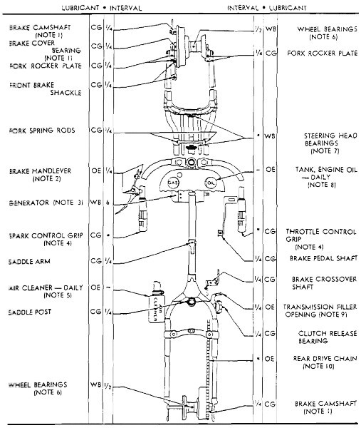
20. LUBRICATION GUIDE (fig. 10).
a. General. Lubrication instructions for this materiel are consolidated in a Lubrication Guide (fig. 10). These specify the points to be lubricated, the periods of lubrication, and the lubricant to be used. Intervals indicated on the guide are for normal service. For extreme conditions, high speed, heat, mud, snow, rough roads, dust, etc., change engine oil and lubricate more frequently. In addition to the items on the guide, brake, gear shifter, clutch control linkage, and hinges must be lubricated at frequent intervals.
b. Supplies. In the field it may not be possible to supply a complete assortment of lubricants called for by the Lubrication Guide to meet the recommendations. It will be necessary to make the best use of those available, subject to inspection by the officer concerned, in consultation with responsible ordnance personnel.
c. Lubrication Notes. The following notes apply to the Lubrication Guide (fig. 10). All note references in the guide itself are to the steps below having the corresponding number:
(1) Brake Fittings. Exercise caution when lubricating brake operating cams and front brake cover bushing, as excess grease working out of these bearings is likely to get onto brake lining, reducing brake efficiency. CAUTION: When using air‐operated grease gun, make sure not to overlubricate brake fittings.
(2) Brake Hand Lever Oilcan Points. Oil hand lever fittings and “oiler” mounted on cable housing. Oil front brake control cable at ends of control cable housing.
(3) Generator Commutator End Bearing. Hand‐pack with general purpose grease, No. 2, at temperatures above zero. Below zero, use lighter grease. This operation requires removal of generator end cover. Bearing outer grease retainer must be loosened and swung aside for access to bearing. If not convenient to grease bearing at specified intervals, at least lubricate with a few drops of engine oil applied to hole in outer grease retainer. Do not overlubricate. CAUTION: Generator regulating brush plate must not be shifted while bearing outer grease retainer is loose (par. 92). Generator drive end bearing requires no attention, since it is lubricated by oil circulating through engine.
——
KEY——
INTERVALS LUBRICANTS ¼—
250 MILES OE—
OIL, ENGINE (CRANKCASE GRADE) ½—
500 MILES CG—
GREASE, GENERAL PURPOSE 1—
1000 MILES No. 1 (ABOVE +32°) 6—
6000 MILES No. 1 OR No. 0 (+32° TO +10°) * L—
SPECIAL LUBRICATION No. 0 (BELOW +10°) CHECK DAILY WB—
GREASE, GENERAL PURPOSE (No. 2) Air Cleaner Engine Oil Tank TABLE OF CAPACITIES WITH RECOMMENDATIONS AT TEMPERATURES SHOWN UNIT CAPACITY ABOVE +32° +32° TO +10° BELOW +10° OIL TANK 1 GALLON OE S.A.E. 50 OE S.A.E. 30 OE S.A.E. 10 TRANSMISSION ¾ pint OE S.A.E. 50 OE S.A.E. 30 OE S.A.E. 10RA PD 310207
Figure 10—Lubrication Guide
(4) Spark and Throttle Control Grips. These grips require disassembly. Twice a year, or whenever grips do not turn freely, indicating need of lubrication, remove grips, clean parts, apply grease, and reassemble (par. 101).
(5) Air Cleaner. Examine oil cup daily for excessive dirt and correct oil level. Under extremely dusty or sandy conditions it may be necessary to clean and refill the air cleaner more than once daily. Refill oil cup to indicated level with engine oil. Drain, clean, and refill oil cup every 250 miles, depending upon operating conditions. Every 1,000 miles (oftener if necessary), remove air cleaner filter units, wash in dry‐cleaning solvent, lubricate, and reassemble (par. 76). NOTE: Early type round cleaner did not have removable filter element. Complete cleaner must be removed to wash element.
(6) Wheel Bearings. When wheel hubs are lubricated at regular 500‐mile interval, 1⁄8 ounce of grease with each greasing is sufficient. This amounts to about 15 shots of the standard 1‐pound air gun, or four strokes with a 1‐pound, hand‐operated gun. If vehicle has been operated in water, wheel hubs submerged, apply hub greasing service immediately afterward (or soon as situation permits). Do not overlubricate wheel hub bearings, as excess grease may work into brake linings, reducing brake efficiency. When using air‐operated grease gun, it is easy to overlubricate wheel hub bearings.
(7) Steering Head Bearings. Every 50,000 miles, repack upper and lower bearings, or whenever there is occasion to remove rigid fork for repair or replacement (par. 98).
(8) Tank, Engine Oil. Oil tank is located on right side of motorcycle. Empty tank holds 1 U. S. gallon. Check daily and add engine oil as necessary to refill tank within 1 inch of top. Oil level gage rod (dip stick) is located directly below tank cap. When oil level is down to “REFILL” mark on gage rod, 2 U. S. quarts may be added. Drain oil tank every 1,000 miles and refill with fresh engine oil. Drain plug located on underside of tank in forward position. In extremely dusty service, and in winter weather, change oil oftener.
(a) Winter Caution. Water is a by‐product of combustion in any internal combustion engine. In a condensed state, the water vapor formed would equal approximately the quantity of gasoline burned. Some of this water vapor escapes past the rings into the crankcase. When starting and warming up in cold weather, considerable vapor getting into crankcase condenses to water before crankcase is hot enough to exhaust the vapor, without inside condensation, through outside breather. If engine is driven enough to get crankcase thoroughly warmed up frequently, most of this water is again vaporized and blown out through outside breather. However, a moderately driven engine, making only short runs now and then, and seldom thoroughly warmed up, is likely to accumulate an increasing amount of water in oil tank. This water will, in freezing weather, become slush or ice and, if allowed to accumulate too long, may block oil lines with resulting damage to engine. Also, water mixed with oil for some time, forms a heavy sludge of considerable acid content that is very harmful to bearings and other internal engine parts. To sum it up briefly, an engine that is used only for short runs during freezing weather requires frequent oil changes along with thorough flushing of tank to remove any accumulated sludge.
(9) Transmission Filler Opening. Check oil level in transmission case every 250 miles and add engine oil as necessary to bring level up to filler opening. If motorcycle is run unusually long distances, inspect more frequently. Motorcycle must be on rear stand in straight upright position when checking oil level or filling transmission case. Use same grade of oil used in engine, summer, and winter. If gear shifting difficulty is caused by oil congealing in extremely cold weather, thin oil with small amount of kerosene or dry‐cleaning solvent. Every 1,000 miles, drain and refill transmission to level of transmission filler plug opening with specified grade of engine oil. Transmission holds ¾ pint of oil. To drain transmission case remove filler plug and lay motorcycle on right side. CAUTION: Do not leave motorcycle on side longer than two minutes.
(10) Drive Chains.
(a) Front and rear drive chains are automatically supplied with lubrication by engine oil pumps. Chain oilers are adjustable and may need occasional readjustment to meet lubrication requirements of varied operating conditions. Every 1,000 miles (or more often if operating conditions are extremely severe) inspect front primary drive chain for adequate lubrication (fig. 36).
(b) At every 1,000‐mile period rear drive chain should have additional lubrication as follows: Remove chain, wash thoroughly in dry‐cleaning solvent and hang it up to dry. Then soak chain in SAE 10 engine oil for a short period of time to allow oil to penetrate into all chain bearings. Drain chain and wipe off excess oil. Install rear chain (par. 63). (This attention is not required by front chain.) Readjustment of chain oilers must be made only by organization mechanic (par. 61). CAUTION: Inspect frequently and make sure that rear chain oiler supply pipe is clear, not bent or damaged.
d. Before Applying Lubricant. Always wipe dirt from the lubrication fittings or plugs so that dirt will not enter with the lubricant. Lubricate all chassis points after washing vehicle or after vehicle has been operated in streams or extremely muddy or slushy roads. CAUTION: It is extremely important that high‐pressure cleaning streams or steam should not be directed against ends of wheel hubs, brake side cover bearings, air cleaner, handle bar grips, or electrical system. To do so will seriously affect correct lubrication and functioning of these parts.
e. Oilcan Points. All brake, transmission, and clutch control points not fitted with grease connections should be lubricated with engine oil. Front brake control cable, spark, and throttle control wires must be oiled at the ends of their respective housings, especially after washing vehicle, or after operating it in wet weather. Keep battery terminal felt washers saturated with engine oil to prevent corrosion of connections.
f. Warning Light. Action of the engine oil feed pump is indicated by red signal light in instrument panel. Rider must be thoroughly familiar with operating characteristics of this signal light, to judge condition of engine oil circulating system (par. 7 f).
19. INTRODUCTION.
20. LUBRICATION GUIDE (fig. 10).
92. ARMATURE BEARING SPECIAL LUBRICATION (fig. 57).
101. HANDLE BAR CONTROLS (figs. 66 and 67).
76. AIR CLEANER (figs. 46 and 47).
98. FORKS (figs. 63 and 64).
63. REPLACEMENT OF REAR CHAIN (fig. 41).
61. CHAIN OILERS (fig. 40).
Section VI
TOOLS AND EQUIPMENT STOWAGE ON THE VEHICLE
Paragraph Vehicle tools
21Vehicle equipment
22Vehicle spare parts
23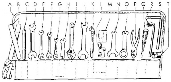
RA PD 310208
Figure 11—Vehicle Tools
21. VEHICLE TOOLS (fig. 11).
a. Kits. Included in the tool kit assembly are the following:
Legend Letter for Fig. 11 Tool Number Carried Mfr’s Number Federal Stock Number Where CarriedA
Tool roll
1
11819–44
——In saddle bag
B
Irons, tire
2
11551–X
41–I–773–75
In tool roll
*C
Handle, chain tool
1
11817–40
41–H–1510–400
In tool roll
D
Wrench, 5⁄8–in. by ¾–in.
1
11804–44C
——In tool roll
E
Wrench, ½–in. by 9⁄16–in.
1
11804–44B
——In tool roll
F
Wrench, 7⁄16–in. by ½–in.
1
11804–44A
——In tool roll
G
Wrench, 5⁄16–in. by 3⁄8–in.
1
11804–44
——In tool roll
H
Wrench, ⅜–in. by 7⁄16–in. (valve tappet)
1
11905–X
——In tool roll
I
Wrench, adjustable
1
11813–44
——In tool roll
*J
Wrench, ¾–in. by 1¾–in. (rear axle nut and trans.)
1
11814–35
41–W–1989–850
In tool roll
K
Gage, tire
1
11562–43
——In tool roll
*L
Tool, chain repair
1
12039–38
——In tool roll
*M
Washers, 0.002–in. thick (chain oiler adj.)
4
674–32
——In tool roll
*N
Wrench, 7⁄16–in. by 1⅜–in. (valve cover)
1
11806–31
41–W–3617
In tool roll
*O
Wrench, 7⁄16–in. by 11⁄8–in. (use with spark plug socket)
1
11929–39
——In tool roll
*P
Pliers, adjustable
1
11812–44
——In tool roll
*Q
Screwdriver
1
11811–X
——In tool roll
R
Wrench, 9⁄16–in. socket (cyl. head bolt)
1
12047–30A
41–W01525
In tool roll
*S
Wrench, wheel mounting
1
11815–35
41–W–3825–400
In tool roll
*T
Wrench, socket (spark plug; use with O)
1
11805–40
41–W–3332
In tool roll
Pump, tire
1
11553–41M
8–P–4900
On frame, left side
Grease gun (in case)
1
11661–38A
——In saddle bag
*EXCEPTION: Earlier models furnished with smaller tool roll and kit contain the items marked by asterisk.
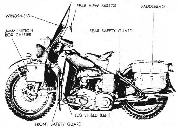
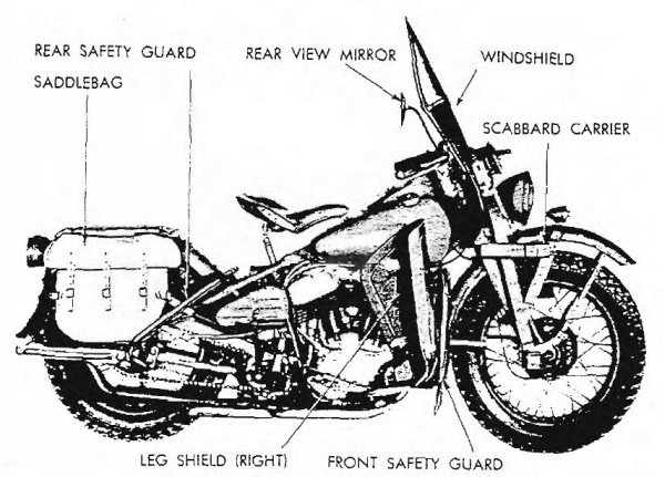
22. VEHICLE EQUIPMENT (figs. 12 and 13).
a. Attached to Vehicle.
Item Number Carried Where CarriedSaddlebags
2
On luggage carrier
Mirror, rear view
1
On left handle bar
Box, submachine gun ammunition
1
Front fender, left side
Bracket, submachine gun carrier
1
Front fender, right side
Guard, front safety
1
Attached to frame
Guard, rear safety
1
Attached to frame
Windshield, cpt
1
On handle bar
Leg shields, cpt (right and left)
2
Attached to frame
RA PD 310216
Figure 12—Vehicle Equipment, Left Side
RA PD 310217
Figure 13—Vehicle Equipment, Right Side
RA PD 310209
Figure 14—Vehicle Spare Parts
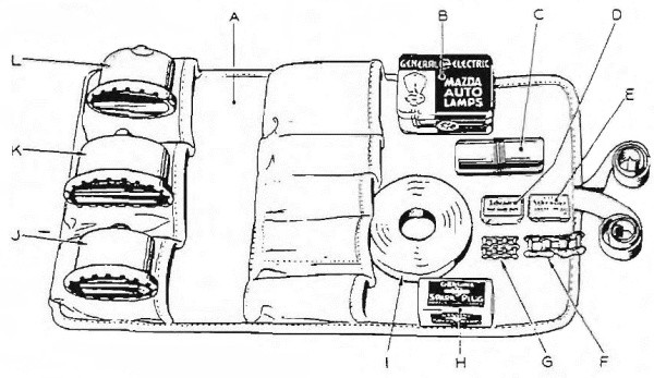
23. VEHICLE SPARE PARTS (fig. 14).
3a. Spare Parts.
Item Number Carried Where CarriedA
Roll, parts kit
1
In saddlebag
H
Plug, spark (and gasket)
1
In kit roll
F
Link, rear chain repair
1
In kit roll
G
Link, front chain repair
1
In kit roll
K
Lamp‐unit, tail blackout
1
In kit roll
J
Lamp‐unit, stop blackout
1
In kit roll
L
Lamp‐unit, tail and stop
1
In kit roll
B
Lamp bulk kit, head lamps, 5 bulbs
1
In kit roll
C
Kit, tire repair
1
In kit roll
I
Tape, friction
1
In kit roll
D
Caps, tire valve (5 in box)
1
In kit roll
E
Cores, tire valve (5 in box)
1
In kit roll
3 EXCEPTION: No spare parts kit supplied with earlier models. Rear chain repair link only spare part furnished.
21. VEHICLE TOOLS (fig. 11).
22. VEHICLE EQUIPMENT (figs. 12 and 13).
23. VEHICLE SPARE PARTS (fig. 14).
RA PD 310216
Figure 12—Vehicle Equipment, Left Side
RA PD 310217
Figure 13—Vehicle Equipment, Right Side
3 EXCEPTION: No spare parts kit supplied with earlier models. Rear chain repair link only spare part furnished.
3a. Spare Parts.
PART TWO—VEHICLE MAINTENANCE INSTRUCTIONS
Section VII
MAINTENANCE ALLOCATION
Paragraph Scope
24Allocation of maintenance
2524. SCOPE.
a. The scope of maintenance and repair by the crew and other units of the using arms is determined by the availability of suitable tools, availability of necessary parts, capabilities of the mechanics, time available, and the tactical situation. All of these are variable and no exact system of procedure can be prescribed.
25. ALLOCATION OF MAINTENANCE.
a. Indicated below are the maintenance duties for which tools and parts have been provided for the using arm and maintenance personnel. Replacements and repairs which are the responsibility of ordnance maintenance personnel may be performed by using arm personnel when circumstances permit, within the discretion of the commander concerned. Echelons and words as used in this list of maintenance allocations are defined as follows:
First and Second Echelon:
Table III
AR 850–15
Operating organization driver, operator or crew, companies and detachments, battalions, squadrons, regiments, and separate companies and detachments (first and second echelons, respectively).
Third Echelon:
Table III
AR 850–15
Technical light and medium maintenance units, including post and port shops.
Fourth Echelon:
Table III
AR 850–15
Technical heavy maintenance and field depot units including designated post and service command shops.
Fifth Echelon:
Table III
AR 850–15
Technical base units.
Service:
(Including preventive maintenance) par. 24 a (2) and (3) in part AR 850–15
Checking and replenishing fuel, oil, grease, water and antifreeze, air, and battery liquid; checking and tightening nuts and bolts; cleaning.
Service:
(Including preventive maintenance) par. 24 a (2) and (3) in part AR 850–15
Checking and replenishing fuel, oil, grease, water and antifreeze, air, and battery liquid; checking and tightening nuts and bolts; cleaning.
Replace:
Par. 24 a (5)
AR 850–15
To remove an unserviceable part, assembly, or subassembly from a vehicle and replace it with a serviceable one.
Repair:
Par. 24 a (6) in part
AR 850–15
To restore to a serviceable condition, such parts, assemblies or subassemblies as can be accomplished without completely disassembling the assembly or subassembly, and where heavy riveting, or precision machining, fitting, balancing, or alining is not required.
Rebuild:
Par. 24 a (6)
AR 850–15
Consists of stripping and completely reconditioning and replacing in serviceable condition any vehicle or unserviceable part, subassembly, or assembly of the vehicle, including welding, riveting, machining, fitting, alining, balancing, assembling, and testing.
Reclamation:
AR 850–15 Par. 4 (c) in part CIR. 75, dated 16 March ’43
Salvage of serviceable or economically repairable units and parts removed from vehicles, and their return to stock. This includes the process which recovers and/or reclaims unusable articles or component parts thereof and places them in a serviceable condition.
NOTES: (1) Operations allocated will normally be performed in the echelon indicated by X.
(2) Operations allocated to the third echelon as indicated by E may be performed by these units in emergencies only.
(3) Operations allocated to the fourth echelon by E are normally fifth echelon operations. They will not be performed by the fourth echelon, unless the unit is expressly authorized to do so by the chief of the service concerned.
CLUTCH
2nd 3rd 4th 5thBearings, clutch release—replace
X
Clutch—replace and/or repair (reline)
X
Hub, clutch—replace
X
Hub, clutch—repair
X
Sprocket assembly, clutch—replace
X
Sprocket assembly, clutch—repair
X
CONTROLS AND LINKAGE
Controls and linkage—service and/or replace
X
Controls and linkage—repair
X
ELECTRICAL GROUP
Battery—service (recharge) and/or replace
X
Battery—repair
X
Battery—rebuild
E
X
Cables, battery—replace and/or repair
X
Coil, ignition—replace
X
Head, speedometer—replace
X
Head, speedometer—repair
X
Head, speedometer—rebuild
X
Horn assembly—replace
X
Horn assembly—repair
X
Light assemblies—service and/or replace
X
Light assemblies—repair
X
Panel, instrument—replace
X
Panel, instrument—repair
X
Switch assemblies—replace
X
Switch assemblies—repair
X
Wiring—replace
X
ENGINE
(V–45″–Twin Engine)
Bearings, main—replace
E
X
Bearings, connecting rod—replace
E
X
Breaker assembly, circuit—replace
X
Breaker assembly, circuit—repair
X
Breaker assembly, circuit—rebuild
X
Carburetor—replace
X
Carburetor—repair
X
Carburetor—rebuild
X
Cleaner, air—service and/or replace
X
Cleaner, air—repair
X
Cleaner, air—rebuild
X
Cylinder assembly—replace
X
Cylinder assembly—repair
X
Cylinder assembly—rebuild (recondition)
E
X
Condenser—replace
X
Engine assembly—replace
*
4X
Engine assembly—repair
X
Engine assembly—rebuild
E
X
Gasket, cylinder head—replace
X
Gears, timing—replace
E
X
Generator assembly—replace
X
Generator assembly—repair
X
Generator assembly—rebuild
X
Head, cylinder—replace and/or repair
X
Lines and connections—replace
X
Lines and connections—repair
X
Pistons, rings and pins assembly—replace
E
E
X
Plug, spark—replace
X
Points, circuit breaker—service and/or replace
X
Pump assembly, feed—replace
X
Pump assembly, feed—repair
X
Pump assembly, feed—rebuild
X
Pump assembly, oil—replace
X
Pump assembly, oil—repair
X
Pump assembly, oil—rebuild
X
Pump assembly, oil scavenger—replace and/or repair
X
Pump assembly, oil scavenger—rebuild
X
Rod, connecting—replace and/or rebuild (recondition)
X
X
Sprocket, engine—replace
X
Strained gasoline—replace and/or repair
X
Valves—service
X
EXHAUST GROUP
Muffler and exhaust pipe—replace
X
Muffler and exhaust pipe—repair
X
MISCELLANEOUS
Bars, safety—replace
X
Bars, safety—repair
X
Boxes, ammunition, battery and tool—replace
X
Boxes, ammunition, battery and tool—repair
X
Carriers, luggage and scabbard—replace
X
Carriers, luggage and scabbard—repair
X
Frame—replace and/or rebuild
E
X
Guards, mud—replace
X
Guards, mud—repair
X
Plate, skid—replace
X
Plate, skid—repair
X
Saddle—replace
X
Saddle—repair
X
Saddle—rebuild
X
Springs, saddle post—replace
X
Tank, fuel—replace
X
Tank, fuel—repair
X
Tank, oil—replace
X
Tank, oil—repair
X
SUSPENSION (FRONT)
Bars, handle—replace
X
Bars, handle—repair
X
Damper, steering—replace
X
Drum, brake—replace
X
Fork, front assembly—replace
X
Fork, front assembly—repair
X
Fork, front assembly—rebuild
X
Fork, spring—replace
X
Fork, spring—repair
X
Fork, spring—rebuild
X
Plate, rocker—replace
X
Plate, rocker—repair
X
Shoe assembly, brake—service and/or replace
X
Shoe assembly, brake—repair (reline)
X
Springs, cushion and rebound—replace
X
SUSPENSION (REAR)
Chains, all—replace and/or repair
X
Drum, brake, rear—replace
X
Guards, chains—replace
X
Guards, chains—repair
X
Shoe assemblies, brake—service and/or replace
X
Shoe assemblies, brake—repair (reline)
X
Sprocket, rear—replace
X
Wheels—replace
X
Wheels—repair
X
Wheels—rebuild
E
X
TIRES
Casings and tubes—replace
X
Casings—repair
E
X
Tubes, inner—repair
X
TRANSMISSION
Spring, kick starter—replace
X
Sprocket, transmission countershaft—replace
X
Starter, kick—replace
X
Starter, kick—repair
X
Transmission—replace
*
4X
Transmission—repair
X
Transmission—rebuild
E
X
VEHICLE ASSEMBLY
Motorcycle—service
X
Motorcycle—rebuild (with serviceable unit assemblies)
X
E
4 The second echelon is authorized to remove and reinstall items marked by an asterisk. However, when it is necessary to replace an item marked by an asterisk with a new or rebuilt part, subassembly or unit assembly, the assembly marked by an asterisk may be removed from the vehicle by the second echelon only after authority has been obtained from a higher echelon of maintenance.
24. SCOPE.
25. ALLOCATION OF MAINTENANCE.
4 The second echelon is authorized to remove and reinstall items marked by an asterisk. However, when it is necessary to replace an item marked by an asterisk with a new or rebuilt part, subassembly or unit assembly, the assembly marked by an asterisk may be removed from the vehicle by the second echelon only after authority has been obtained from a higher echelon of maintenance.
Section VIII
SECOND ECHELON PREVENTIVE MAINTENANCE
Paragraph Second echelon preventive maintenance services
2626. SECOND ECHELON PREVENTIVE MAINTENANCE SERVICES.
a. Regular scheduled maintenance inspections and services are a preventive maintenance function of the using arms, and are the responsibility of commanders of operating organizations.
(1) Frequency. The frequencies of the preventive maintenance services outlined herein are considered a minimum requirement for normal operation of vehicles. Under unusual operating conditions such as extreme temperatures, and dusty or sandy terrain, it may be necessary to perform certain maintenance services more frequently.
(2) First Echelon Participation. The drivers should accompany their vehicles and assist the mechanics while periodic second echelon preventive maintenance services are performed. Ordinarily the driver should present the vehicle for a scheduled preventive maintenance service in a reasonably clean condition; that is, it should be dry, and not caked with mud or grease to such an extent that inspection and servicing will be seriously hampered. However, the vehicle should not be washed or wiped thoroughly clean, since certain types of defects, such as cracks, leaks, and loose or shifted parts or assemblies are more evident if the surfaces are slightly soiled or dusty.
(3) If instructions other than those contained in the general procedures in paragraph (4) or the specific procedures in paragraph (5) which follow, are required for the correct performance of a preventive maintenance service, or for correction of a deficiency, other sections of the vehicle operator’s manual pertaining to the item involved, or a designated individual in authority, should be consulted.
(4) General Procedures. These general procedures are basic instructions which are to be followed when performing the services on the items listed in the specific procedures. The second echelon personnel must be thoroughly trained in these procedures so that they will apply them automatically.
(a) When new or overhauled subassemblies are installed to correct deficiencies, care should be taken to see that they are clean, correctly installed, properly lubricated, and adjusted.
(b) When installing new lubricant retainer seals, a coating of the lubricant should be wiped over the sealing surface of the lip of the seal.
(c) The general inspection of each item applies also to any supporting member or connection, and usually includes a check to see whether the item is in good condition, correctly assembled, secure, or excessively worn. The mechanics must be thoroughly trained in the following explanations of these terms:
1. The inspection for “good condition” is usually an external visual inspection to determine whether or not the unit is damaged beyond safe or serviceable limits. The term “good condition” is explained further by the following: not bent or twisted, not chafed or burned, not broken or cracked, not bare or frayed, not dented or collapsed, not torn or cut.
2. The inspection of a unit to see that it is “correctly assembled” is usually an external visual inspection to see whether or not it is in its normal assembled position in the vehicle.
3. The inspection of a unit to determine if it is “secure” is usually an external visual examination, a hand‐feel, or a pry‐bar check for looseness; such an inspection should include any brackets, lock washers, lock nuts, locking wires, or cotter pins used in assembly.
4. “Excessively worn” will be understood to mean worn, close to or beyond serviceable limits, and likely to result in a failure if not replaced before the next scheduled inspection.
(d) Special Services. These are indicated by repeating the item numbers in the columns which show the interval at which the services are to be performed, and show that the parts, or assemblies, are to receive certain mandatory services. For example, an item number in one or both columns opposite a Tighten procedure, means that the actual tightening of the object must be performed. The special services include:
1. Adjust. Make all necessary adjustments in accordance with the pertinent section of the vehicle operator’s manual, special bulletins, or other current directives.
2. Clean. Clean units of the vehicle with dry‐cleaning solvent to remove excess lubricant, dirt, and other foreign material. After the parts are cleaned, rinse them in clean dry‐cleaning solvent, and dry them thoroughly. Take care to keep the parts clean until reassembled, and be certain to keep dry‐cleaning solvent away from rubber or other material which it will damage. Clean the protective grease coating from new parts, since this material is not a good lubricant.
3. Special lubrication. This applies both to lubrication operations that do not appear on the vehicle Lubrication Guide, and to items that do appear on such guides, but should be performed in connection with the maintenance operations, if parts have to be disassembled for inspection or service.
4. Serve. This usually consists of performing special operations, such as replenishing battery water, and draining and refilling units with oil.
5. Tighten. All tightening operations should be performed with sufficient wrench‐torque (force on the wrench handle) to tighten the nut according to good mechanical practice. Use torque‐indicating wrench where specified. Do not overtighten, as this may strip threads, or cause distortion. Tightening will always be understood to include the correct installation of lock washers, lock nuts, and cotter pins provided to secure the tightening.
(e) When conditions make it difficult to perform the complete preventive maintenance procedures at one time, these can sometimes be handled in sections, planning to complete all operations within the task if possible. All available time at halts and in bivouac areas must be utilized, if necessary, to assure that maintenance operations are completed. When limited by the tactical situation, items with special services in the columns should be given first consideration.
(f) The numbers of the preventive maintenance procedures that follow are identical with those outlined on W.D. AGO Form No. 463, which is the Preventive Maintenance Service Work Sheet for Motorcycles. Certain items on the work sheet that do not apply to this vehicle are not included in the procedures in this manual. In general, the numerical sequence of items on the work sheet is followed in the manual procedures, but in some instances there is deviation for conservation of the mechanic’s time and effort.
(5) Specific Procedures. The procedures for performing each item in the 1,000‐mile maintenance procedures are described in the following chart. Each page of the chart has a column at its left edge corresponding to the 1,000‐mile maintenance.
ROAD TEST
1000 Mile Maintenance NOTE: If tactical situation does not permit a full road test, perform items 2, 3, 4, 5, 6, 7, 8, 9, 12, and 14, which require slight or no movement of the vehicle. When a road test is possible, it should be for preferably 5, and not over 10 miles.1
Before‐operation Inspection.Perform Before‐operation Service listed on W.D. Form No. 418. “Driver’s Trip Ticket and Preventive Maintenance Service Record” (described in par. 15), to determine if vehicle is in a satisfactory condition to make the road test safely.
2
Ease of Starting.Start engine and observe action of starter. Note if engine responds readily.
3
Oil Circulation.Oil circulation is normally indicated by oil signal light (red light) in instrument panel being out. When red light is on, oil is not circulating. Observe for
excess smoke in exhaust. CAUTION:
If red light fails to go out after engine has been started, stop engine at once. Refer to paragraph 30 for possible causes.4
Instruments.Observe instruments for proper or normal indication and functioning of system to which they apply.
Speedometer and Odometer.Speedometer must indicate vehicle speed without excessive noise or fluctuation; odometer must record trip and total mileage.
Oil Pressure Signal Light.Note whether oil signal light (red light) indicates correctly. After ignition switch is turned on, and before starting engine, the red light should go on, indicating no oil circulation. When engine is started, light should go out.
Generator Signal Light.With switch on, and before starting engine, the green signal light should go on, indicating discharge of battery. After starting engine, increase engine speed to a medium fast idle; green signal light should then go out, indicating generator is charging battery. CAUTION:
Continue observation of signal lights during road test, and if lights should fail to operate as indicated above, stop engine, investigate cause, and correct or report trouble to proper authority.5
Brake Operation.Test foot brake for safe stop within reasonable distance. Note squeaks or chatter that might indicate wet, oily, dirty, or loose lining, damaged drum, or improper adjustment. Apply hand‐operated front brake only in conjunction with rear brake and observe whether it operates effectively in assisting to make a quicker stop.
6
Clutch Operation.Before moving vehicle, make sure that clutch pedal has satisfactory free travel before it begins to disengage clutch; that it releases clutch completely before reaching end of travel; and that there are no unusual noises in clutch‐release mechanism. When starting vehicle, observe whether clutch grabs, chatters, or slips when fully engaged.
7
Gearshift.Shift through entire gear range of transmission and observe whether mechanism operates freely without clashing or jumping out of gear. Note any unusual vibration that might indicate loose engine or transmission mountings.
8
Unusual Noises.During entire road test, listen for unusual noises that might indicate worn, loose, damaged, or insufficiently lubricated parts in the entire motorcycle, particularly in engine and accessories, or in the power train.
CAUTION:
Loose primary (front) drive chain, with slack in excess of ½ inch total up‐and‐down motion, can cause excessive noise which sounds like engine knock. Remove inspection cover for examination of chain.9
Steering.Observe steering mechanism for indication of looseness or excessive binding through full turning range. With hands resting lightly on handle bars and vehicle in vertical position, observe whether there is any tendency to pull to one side when operating at a reasonable speed. Note any indication of steering instability at higher speeds.
10
Balance.If vehicle does not balance properly in operation, inspect for misalinement of rear wheel.
11
Speedometer and Odometer.Inspect speedometer for proper operation, excessive fluctuation, or unusual noise. Observe odometer for correct recording of trip and total mileage.
12
Throttle and Spark Controls.Set throttle stop screw and low speed needle adjustment so that engine will operate smoothly and will not stall at idling speed. With vehicle running at a speed of 30 miles per hour, or faster, in high gear, turn throttle control grip to “OPEN” and “CLOSED” positions and note whether engine responds instantly to throttle changes. Turn spark control grip and note whether it fully advances and retards ignition timer.
13
Power and Operation.Observe engine for normal pulling power, and good operating characteristics in each speed, from first to high gear. Also observe whether engine misses, stalls, knocks excessively, or makes any other unusual noise.
14
Carburetor Adjustment.No carburetor adjustment, other than idle adjustment as performed in item 12, is required on this vehicle.
15
Brake Drum and Hub Temperature.Immediately after completing road test, feel front and rear brake drums and wheel hubs for overheating.
16
Power Train Temperatures.Feel transmission for overheating.
MAINTENANCE OPERATION17
Compression Test.With throttle wide‐open, test compression with starter. If engine lacks compression, inspect for leaks.
18
Transmission.Inspect transmission for good condition, secure mounting, and leaks. Inspect oil level. Drain and refill
transmission to level of transmission filler plug opening with specified grade of engine oil. CAUTION:
Always drain transmission immediately after it has been warmed and agitated by operation of engine. Refill as soon as draining is completed to avoid hazard of operating without lubricant. Tighten all mounting and assembly bolts securely.20
Engine Oil.Inspect oil tank for oil level: drain and refill tank. CAUTION:
Fill to within 1 inch of filler opening and filler cap with specified weight of oil. Always drain immediately after engine operation and refill as soon as draining is completed, to avoid hazard of operating without lubricant.21
Battery and Carrier.Clean top of battery. See that battery and carrier are in good condition, and that carrier is securely mounted. Remove cell caps: make sure that vents are open. Test specific gravity with hydrometer and record readings on work sheet, W.D. AGO Form No. 463. Readings below 1.225 indicate need for recharge, or battery failure. Variation between cells of more then 0.025 must be reported. Read and record voltage of battery (6‐volt reading is normal). Bring electrolyte to
5⁄
16inch above tops of plates, using clean, drinkable water. If excessive looseness of battery in case is noted, check for presence of rubber pad in bottom of case, and make sure rubber pad is installed on top of battery, when battery service is completed.
22
Battery Wires and Terminals.Inspect battery for good condition and secure connections. Look for worn spots in wire insulation. Oil the felt washers on battery terminals.
23
Electrical Wiring.Inspect all electric wiring to see that it is in good condition, securely attached, and connected. Look for worn spots in insulation.
24
Generator Drive and Mounting, and Relay.Inspect generator for secure mounting. After removing left footboard assembly, remove generator and cover. Examine commutator for cleanliness, good condition, or excessive wear. If commutator is dirty, it must be cleaned with No. 00 sandpaper. Blow out with compressed air. If commutator is in bad condition or excessively worn, replace generator. Remove relay cover, being careful to avoid damage to mechanism, and inspect for cleanliness. Blow out with air if wet or dirty. CAUTION:
Do not attempt to adjust relay, or to clean it in any other manner.25
Timer(
Circuit Breaker). Clean and remove timer cover. See that wiring leads are securely connected and that inside
of the timer is clean. Inspect breaker points to see that they are clean, well‐lined, engaging squarely, and are not excessively pitted, burned, or worn. See that condenser mounting screw is tight. Breaker lever should be free on its pivot and well insulated from the pivot pin. Determine if breaker arm spring exerts normal force against arm. Examine camshaft by hand‐feel to see whether it is excessively worn in its bushings; if camshaft bushings are worn excessively, install new timer. If points are slightly burned or pitted, dress them with a fine file. If breaker points are unserviceable, install a new set, taking care to aline them and to adjust gap to 0.022 inch. Apply one drop of oil to breaker arm pivot pin. Use clean cloth to wipe cam and then coat with a very light film of light grease. CAUTION:
Be careful to avoid getting oil or grease on breaker points.26
Spark Plugs.Remove spark plugs, clean with sandblast cleaner, and inspect for cracked insulators: inspect electrodes for good condition and adjust gap to 0.025 to 0.030 inch; replace faulty plugs. Be sure to install new gasket with new plug. Inspect radio suppressors on plug cables for good condition and secure attachment.
27
Ignition and Light Switch.Make sure that the switch is in good condition and operating properly in all positions.
28
Lights, Service and Blackout.See that all lights are clean, in good condition, properly aimed, and securely mounted. Tactical situation permitting, turn switch to each of its positions and observe whether service and blackout lights operate properly, and whether they go out when switched off. Operate dimmer switch on left handle bar to see whether it depresses beam of service headlight. Apply foot brake for check of both blackout and service stop light operation. Inspect lenses for breakage, and headlight reflector for discoloration. Clean all lenses.
29
Horn.Tactical situation permitting, sound horn to test for normal signal. Examine horn for good condition, secure mounting, and tight wiring connections.
30
Cylinder Heads.If cylinder head gaskets show signs of leakage, tighten head bolts: if leakage persists, new gaskets should be installed. A head bolt wrench (Fed‐Stock No. 41–W–1525) is available with which head bolts can be tightened without removing tanks for wrench clearance. If tanks are removed to permit taking off heads and installing
new gaskets, bolts should then be tightened evenly with a torque wrench to a tension of 60 foot‐pounds minimum, or 65 foot‐pounds maximum, when engine is cold.
31
Cylinder Hold‐down Nuts.If these nuts are loose, or there is excessive oil leakage around cylinder bases, tighten nuts evenly when engine is cold. If excessive leakage persists, new gaskets should be installed. CAUTION:
If cylinder base nuts are loose, perform item 36 before starting engine.32
Engine Mountings.Inspect top engine mounting bracket and bolt for good condition and security. CAUTION:
Tight seating of the engine bracket mounting bolt is a necessity for effective radio bonding. Inspect four lower engine mounting bolts for signs of looseness. Tighten as required.33
Engine Crankcase.Examine engine crankcase for good condition and for leaks. Make sure timing gear cover screws, and oil feed and scavenger pump nuts, are tight.
34
Intake Manifold.Examine manifold for good condition and secure mounting. Make sure manifold nuts are tight.
35
Muffler and Exhaust Pipes.Inspect muffler and exhaust pipes for good condition, secure mounting, and for leaks. Be sure tail pipe opening is not restricted.
36
Valve Mechanism.When engine is cold, adjust valve tappet clearance to 0.004–inch minimum, 0.005–inch maximum on intake valve; 0.006–inch minimum, 0.007–inch maximum on exhaust valve. See that valve springs are in good condition and properly secured; that valve tappet adjusting screws and lock nuts are in good condition; and that valve covers are in good condition, secure, and not leaking oil.
37
Starter.Examine pedal, crank, and return spring for good condition, correct assembly, and secure mounting. Starter should operate without binding, and return spring should bring starter crank to its disengaged position when foot pressure is removed. CAUTION:
Make sure that starter crank pinch bolt is installed with head of bolt toward rear of vehicle when crank is in upright position.38
Engine Cooling Fins.Inspect engine cooling fins for good condition and cleanliness. Remove all dirt or foreign matter. Do not apply paint to cooling fins.
39
Filler Caps and Vents.Wipe dirt and dust from filler caps of fuel and oil tanks. Inspect caps and gaskets to see that they are in good condition. Note whether vent in fuel filler
cap is open. Reinstall caps, observing that each locks properly on filler neck. Do not interchange fuel and oil tank filler caps.
40
Fuel Tank Valves and Lines.See that valves and lines are in good condition, secure, and not leaking. Test fuel shut‐off valve for ample friction to hold valve in reserve position. See that valve lifts freely enough to operate satisfactorily.
41
Oil System Leaks.Examine oil tank, oil lines, vent line, and connections for good condition, secure attachment, and for leaks.
42
Carburetor and Fuel Filter(
Gasoline Strainer). Examine carburetor and fuel filter for good condition, secure connections, and for leaks. Shut off fuel tank valve and remove filter (strainer) cap and screen. Wash cap and screen in dry‐cleaning solvent, and open shut‐off valve slightly to flush filter body. Reassemble screen, gaskets, and cap, being careful not to damage gaskets. Use new gaskets if necessary. Drain water and foreign matter from carburetor bowl by removing bowl drain plug. Open shut‐off valve slightly to flush carburetor bowl while plug is out. Replace plug, being careful to avoid crossing threads. Open fuel tank shut‐off valve and check for leaks.
43
Air Cleaner.Remove oil cup; inspect condition of oil, and amount of sediment. If service is required, remove filter elements, clean and fill cup to NORMAL level. Wash elements in dry‐cleaning solvent, dry thoroughly with compressed air, immerse each element in oil in cup, and reassemble elements and oil cup to air cleaner body immediately. Make sure gaskets are in good condition. NOTE:
Early type round cleaner does not have removable filter element; therefore, the complete cleaner body must be removed to wash element.44
Gearshift Lever and Linkage.See that gearshift lever and linkage are in good condition, secure, and not excessively worn. Lubricate all joints with a few drops of engine oil. Adjust shifter lever so that when moved to any gear position in shifter guide on tank, the transmission is shifted to full engagement in corresponding gear.
45
Primary Drive.Remove inspection hole cover from front chain guard. With clutch engaged and transmission in neutral, rotate primary chain to position of least slack. Check chain for ½–inch deflection. Deflection measurement should
be total up‐and‐down free movement. Inspect chain for adequate lubrication. Loosen front and rear chain oiler adjusting screws two turns each. Do not remove screws. Idle engine 1 minute, then tighten screws firmly, but do not force. This operation serves to flush control valves and rear chain oiler pipe.
46
Clutch Pedal and Linkage.Inspect clutch pedal clevis connections and cable to see that they are in good condition and not excessively worn. Check free travel of clutch pedal to make sure it is within specified limits. With foot pedal in fully disengaged position (heel against footboard) clutch release lever must clear sprocket cover stud and nut by about
1⁄
16inch: with foot pedal in fully engaged position, clutch release lever must have between
1⁄
8– and ¼–inch of free movement on end of foot pedal cable. Lubricate all joints with a few drops of engine oil, including cable at each end of cable housing.
47
Rear Chain and Guard.Inspect rear chain guard for good condition and secure mounting. Remove chain, wash thoroughly in dry‐cleaning solvent, and hang it up to dry. See that chain is in good condition, not excessively worn, and has no broken rollers on side plates. Soak chain in SAE 10 engine oil for a short period of time to allow oil to penetrate into all rollers; drain chain, and wipe off excess oil. Inspect countershaft sprocket, and rear wheel sprocket to see that they are in good condition, not excessively worn, and that rear sprocket rivets are tight. Do not reinstall chain until item 71 has been performed. When reinstalling chain, make sure that connecting link is in good condition and securely locked. See that open end of connecting link spring clip is trailing in direction of chain travel. Adjust chain (paragraph
60).
48
Final Drive Sprockets.Inspection of final drive sprockets is made when performing item 47.
50
Paint and Markings.Examine vehicle for good condition and see that paint is not rubbed to a polish, and has no bare spots that might rust or reflect light. See that vehicle markings are legible.
51
Frame.Examine frame for good condition; observe whether it seems to be sprung out of alinement.
52
Steering Head and Fork Stem.Raise front end of vehicle by placing blocks under skid plate. Complete all following items to and including item 71, before lowering vehicle to ground. Examine steering head and fork stems for good
condition. Note whether there is up‐and‐down play caused by loose bearings. Move handle bars through complete range and observe if there is any binding which might indicate improperly adjusted or defective bearings.
53
Handle Bars.Examine handle bars for good condition and secure mounting.
54
Throttle Control.See that grip is in good condition, that throttle opens and closes completely as grip is turned to its extreme positions, and that control wire and housing are in good condition and secure. Lubricate lightly through hole in rear of grip to avoid rusting and “freezing.” If grip does not rotate freely, disassemble grip, clean, and lubricate spiral control parts.
55
Spark Control.See that grip is in good condition, that spark is fully advanced and retarded as the grip is turned to its extreme positions; that the control wire and housing are in good condition and secure. Lubricate lightly through hole in rear of grip to avoid rusting and “freezing.” If grip does not rotate freely, disassemble grip, clean, and lubricate spiral control parts.
57
Rear View Mirror.Clean rear view mirror and examine for good condition and secure mounting.
58
Front Fender(
Mudguard). Examine front fender for good condition and secure mounting; see that fender does not scrape tire.
59
Weapon Carrier.Inspect weapon carrier for good condition and secure mounting.
60
Ammunition Box.See that ammunition box and cover are in good condition and securely attached.
61
Front Springs.See that front springs and their mountings are in good condition, correctly assembled, and secure.
62
Front Forks.See that front forks are in good condition and securely mounted.
63
Front Fork Rocker Plates(
Rocker Arms).See that front fork rocket plates are in good condition, secure, and not excessively worn. Tighten rocker plate stud nuts securely.
64
Front Fork Damper.Inspect steering damper for good condition and to see that it operates freely. Observe whether friction disks are glazed, coated with grease, or excessively worn.
65
Front Brake and Control Linkage.See that control linkage operates freely, that all connections are tight, and that
brake is adjusted so that end of hand lever has ¼ free travel before meeting resistance. Look for any indications of a cracked or excessively worn brake drum: badly worn, loose, or grease‐saturated linings. If there are any such indications, remove wheel for closer inspection. Look for badly worn brake side cover bushing, shackle bushings and studs, or brake operating stud bearing. Apply a few drops of engine oil to control cable, especially at control housing oiler at left handle bar, and to pin joints.
66
Front Wheel Alinement and Spokes.Examine front wheel spokes for presence, good condition, and tightness. If loose spokes are found, tighten evenly, taking care not to distort rim out‐of‐round, or to cause run‐out. Examine rim for good condition, and spin wheel to see that it has no appreciable run‐out.
67
Front Wheel Bearings.Inspect wheel to see whether bearings are excessively loose. Wheel should have slight amount of side play at rim. Spin wheel and listen for unusual noises which might indicate dry or defective bearings or races. Observe for excessive grease leak. If wheel is found to need only slight cone readjustment to correct excessive bearing play, remove wheel and make this adjustment (par.
126). If indications are found that hub is otherwise in bad order, replace wheel.
Each Sixth 1,000–Mile Maintenance Service.Remove front wheel, axle sleeve and bearing, and, together with wheel hub, clean thoroughly in dry‐cleaning solvent. Inspect parts for good condition: inspect brake drum. Inspect lining for good condition and secure attachment, and see that it is neither excessively worn nor soaked with grease. Repack bearings, hub, and axle sleeve with specified lubricant. CAUTION:
Make sure that hands and grease are perfectly clean, and that grease is forced between balls onto the cone.Reassemble and adjust bearings according to instructions in paragraph
126, taking care to see that wheel is properly alined. If unusual operating conditions, such as fording streams, have indicated probable contamination of lubricant, this service should be performed more frequently.
68
Front Wheel Axle Nuts.Tighten axle nuts, making sure that cotter pins are installed. Slot in stabilizer plate must be anchored on extended end of left‐front rocker plate stud.
69
Tires, Front and Rear.Gage tires and inflate to 18 pounds front, and 20 pounds rear (cold). Make sure that valve stems are in good condition and correctly installed, and that valve caps are present and secure. Examine tires for
cuts, bruises, breaks, and blisters: remove imbedded glass, nails, or other foreign matter from tire treads; observe treads for excessive or irregular tire wear. At any inspection when unusual or irregular tire wear becomes evident, interchange front and rear tires.
70
Rear Wheel Alinement and Spokes.With vehicle on rear stand, inspect in same manner as front wheel (item 66). If it is necessary to aline wheel in frame, make sure sprockets and chains are in correct alinement.
71
Rear Wheel Bearings and Seals.Inspect wheel to see whether bearings are excessively loose (wheel should have a slight amount of play at rim). Spin wheel and listen for unusual noise which might indicate dry or defective bearings. Also observe whether there is excessive grease leak. Test for excessive end play. If wheel is found to have considerable side play at rim, indicating excessively worn bearings, or there is evidence of hub assembly being in bad order otherwise, replace wheel. If wheel must be replaced, inspect brake drum and lining for good condition, as indicated in item 75, before reinstalling wheel. CAUTION:
Make sure that wheel mounting socket screws are tight.72
Rear Wheel Axle Nut.See that rear wheel axle nut is in good condition and securely tightened.
74
Rear Fender(
Mudguard). Inspect rear fender for good condition and secure attachment.
75
Rear Brake and Control Linkage.See that brake control linkage operates freely, and that all connections are secure. Look for indications of badly worn or grease‐saturated linings. If brake operating lever stands considerably ahead of vertical, excessive lining wear is indicated. If grease has worked out between brake drum and brake cover, grease‐saturated linings are indicated. In either case the wheel should be removed for closer inspection. Inspect drum for cracks or excessive wear. Make sure wheel mounting socket screws are tight. Examine linkage for loose or worn pin or clevis, and for missing washers or cotter pins. Apply a few drops of engine oil to all linkage joints. Brake pedal should have 1–inch free travel before brake begins to meet resistance. Adjust length of brake rod at brake operating lever to provide 1–inch free pedal travel.
77
Footboard and Rest.Examine footboard and rest for good condition and secure attachment.
78
Saddle Spring and Hinge.Examine saddle for good condition and secure mounting, paying particular attention to
torn leather, ripped seams, sagging or broken spring in seat post, and excessive wear in front hinge. CAUTION:
Make sure that spring wire clip properly locks the saddle rear hinge clevis pin.79
Luggage Carrier.Examine luggage carrier for good condition and secure mounting.
80
Saddle Bags.Examine saddle bags for good condition, cleanliness, and secure fastening to luggage carrier. Note particularly whether leather is torn, seams ripped, or straps and buckles missing or damaged.
81
Tools, Tire Pump, and Equipment.Inspect tool kit, tools, tire pump, and other equipment for good condition, cleanliness, serviceability, and proper stowage. Make sure that tire pump is securely clamped to motorcycle frame. Check all items with stowage list (pars.
21,
22and
23). Make sure that vehicle manuals and Accident Report Form No. 26 are present on vehicle and legible.
82
Safety Guards.Inspect safety guards for good condition and secure mounting.
83
Leg Shields.Inspect leg shields for good condition and secure mounting. NOTE:
Motorcycles operating in warm weather should not be equipped with leg shields, as they seriously hamper engine cooling.84
Skid Plate.Examine skid plate for good condition and secure mounting. CAUTION:
Skid plate must be present.85
Vehicle Lubrication.Lubricate all points of vehicle in accordance with instructions in this manual, Lubrication Guide, current lubrication bulletins or directives, and the following instructions:
Any unit that required disassembly for inspection purposes must be lubricated correctly unless the vehicle is to be deadlined for the repair of that unit. Use only clean lubricant. Keep all lubricant containers covered except when used during lubrication. Before applying lubricant, always wipe dirt from the lubrication fitting or plug so that dirt will not enter with the lubricant. If lubricant fittings or plugs are missing or damaged, replace them. Clean the hole in which the fitting is to be installed, and lubricate after the new fitting has been installed.
Lubricant must be applied properly. On unsealed joints or bushings, apply lubricant until it appears at openings. However, lubricate sparingly the front wheel hub, rear wheel hub, front brake side cover bushing, front brake operating
lever stud, and rear brake operating lever stud, to prevent grease reaching brake linings. Rider should be advised whenever wheel bearings are serviced or adjusted, so that during the next road operation he may determine whether bearings or brake drums are running hot, due to overtight adjustment of bearings, or a dragging brake.
Do not apply more than specified amount of lubricant to generator or timer (circuit breaker). To do so may cause failure of the unit.
Wipe off excess applied lubricant that may drip onto brake or operating surfaces, soil clothes, or detract from vehicle’s appearance.
Parts or assemblies that have already been lubricated while disassembled for inspection, gear cases that have been drained and refilled as mandatory items in the procedure, and those parts that have been indicated for special lubrication, will be omitted from the general lubrication of the vehicle.
86
Final Road Test.Make a final road test, reinspecting items 2 to 16, inclusive. Be sure to recheck transmission to see that lubricant is at correct level and not leaking. Confine this road test to the minimum distance necessary to make satisfactory observation. Correct or report all deficiencies found during final road test to designated authority.
26. SECOND ECHELON PREVENTIVE MAINTENANCE SERVICES.
(4) General Procedures. These general procedures are basic instructions which are to be followed when performing the services on the items listed in the specific procedures. The second echelon personnel must be thoroughly trained in these procedures so that they will apply them automatically.
(5) Specific Procedures. The procedures for performing each item in the 1,000‐mile maintenance procedures are described in the following chart. Each page of the chart has a column at its left edge corresponding to the 1,000‐mile maintenance.
30. ENGINE LUBRICATING SYSTEM.
60. ADJUST REAR CHAIN AND ALINE REAR WHEEL (fig. 39).
126. FRONT WHEEL HUB ADJUSTMENT.
21. VEHICLE TOOLS (fig. 11).
22. VEHICLE EQUIPMENT (figs. 12 and 13).
23. VEHICLE SPARE PARTS (fig. 14).