Thermoelectric Microgenerators. Optimization for energy harvesting
Қосымшада ыңғайлырақҚосымшаны жүктеуге арналған QRRuStore · Samsung Galaxy Store
Huawei AppGallery · Xiaomi GetApps

автордың кітабын онлайн тегін оқу  Thermoelectric Microgenerators. Optimization for energy harvesting

Gennady Gromov

Thermoelectric Microgenerators

Optimization for energy harvesting


Contents

  1. Thermoelectric Microgenerators
  2. Preface
  3. Chapter 1. Introduction
  4. Chapter 2. Physical basics
    1. Heat balance equations
    2. Main parameters
    3. Effective thermal conductivity and thermal resistance
  5. Chapter 3. Optimization of electrical circuit
    1. Basic formulas
    2. Maximum power
  6. Chapter 4. Optimization of efficiency
    1. General formula
    2. Maximum efficiency and maximum power modes
    3. Efficiency and carnot cycle
  7. Chapter 5. Optimization of thermal resistance
    1. Thermal resistance
    2. Net power
    3. Maximum power
    4. Physical sense
    5. Particular solutions
    6. Thermal resistance of working generator
  8. Chapter 6. Design optimization
    1. Introduction
    2. Number of thermoelements
    3. Form-factor of thermoelements
    4. Thermal resistance
    5. Coefficient of performance
    6. Heat flow density
  9. Chapter 7. Thermoelectric materials
    1. Typical parameters
    2. Voltage
    3. Maximum power
    4. Coefficient of performance
    5. Efficiency and figure-of-merit
    6. Conclusions
  10. Chapter 8. Interconnection of generators
    1. Connection schemas
    2. Key ratios
    3. Parallel and serial connection
    4. Stack parallel and serial connection
    5. Notes
  11. Chapter 9. Analysis of the environment
    1. Thermal resistance
    2. Example
  12. Chapter 10. DC-DC converters
    1. Introduction
    2. Modern converters
    3. Efficiency of converters
  13. Chapter 11. Bulk or Thin-film
    1. Introduction
    2. Compare electrical characteristics
    3. Coefficient of performance
    4. Conclusions
  14. Chapter 12. Universal series of microgenerators
    1. Introduction
    2. Module design
    3. Geometry of thermoelements
    4. Number of thermoelements
    5. Packing density
    6. Plates
    7. Classification and labelling
    8. Universal series
    9. Standard specification
  15. Chapter 13. Practice nomenclature
    1. Description
    2. Power and dimensions
    3. Power density
    4. Thermal resistance and power
  16. Chapter 14. Thermoelectric coolers as generators
    1. Introduction
    2. Relationship of parameters of cooling and generator modules
    3. General conclusion
  17. Chapter 15. Ideal and real
    1. Introduction
    2. Ideal approach
    3. Real approach
    4. Conclusions
  18. Chapter 16. Universal algorithm
    1. Task statement
    2. Algorithm for calculating
    3. Sample implementation
    4. Algorithm schematics
  19. Chapter 17. Practical tasks
    1. Introduction
    2. Low-power heat sources
    3. Sources of medium temperature difference range
    4. Sources of high temperature difference range
    5. General conclusion
  20. Chapter 18. Examples of energy harvesting
    1. Introduction
    2. The classical task
    3. Built-in generator
    4. Heat source of low heat flow density
    5. Nonstationary heat source
  21. Chapter 19. Equipment for control and researches
    1. Introduction
    2. Measurement of parameters of micromodules
    3. Research equipment
  22. Chapter 20. Markets and applications
    1. Market prospects of energy harvesting
    2. Automotive, transport
    3. Wireless electronic devices and sensors
    4. Miniature radioisotope thermoelectric generators
    5. Utilization of human body heat
    6. Household
    7. Industrial applications, sensors
    8. Other application
  23. Chapter 21. Useful formulas
    1. Heat balance equations
    2. Thermoelectric figure-of-merit
    3. Thermoemf
    4. Electric current
    5. Maximum current
    6. Working voltage
    7. Electrical resistance of the generator
    8. Ratio of load resistance and internal resistance
    9. Net power conversion
    10. Heat flow density
    11. Thermal conductivity of working generator
    12. Thermal resistance
    13. Efficiency
    14. Radiation heat transfer
    15. Heat convection
    16. Generator efficiency and cooling capacity
    17. Current and voltage of generator and cooling capacity
    18. Thermal resistance of generator and cooling mode
    19. Formulas for connections of two generators
  24. List of symbols
  25. Bibliography
  26. Further reading
  27. Annex. Microgenerators universal series
    1. Introduction
    2. Series 1XC06
    3. Series 1XC04
    4. Series 1XD06
    5. Series 1XD04
    6. Series 1XD03
    7. Series 1XDD02

Preface

The idea for this book came from the experience. Our team is in thermoelectric business for over 20 years. Firstly, for many years it was thermoelectric cooling solutions for miniature applications. In recent years, thermoelectrics moves in microgenerators trend. Green energy, energy harvesting…

Promising directions — applications of thermoelectric microgenerators for tasks of low energy — recycling waste heat surrounding thermal sources, of human body energy harvesting and so on.

This direction only began its development. Of course, there are many ideas for development come from inventors and scientists. Often an absence of sufficient knowledge and understanding of the subject of thermoelectricity is compensated by enthusiasm, the broadest fields of promising applications, interesting tasks.

Numerous appeals of such potential consumers to assist them in thermoelectric solutions usually are accompanied by neediness of detailed technical consulting from fundamental physical base of the thermoelectricity phenomenon till fine nuances in their applications.

It has given rise to the idea of writing of the reference book FAQ (Frequently Asking Questions) on the most important questions. Gradually this idea has developed into the separate book on the volume of the reference material.

The structure of this book contains detailed explanations addressed to a wide range of readers, which for the most part are not specialists in the field of thermoelectricity, of the basic ideas, important aspects of the practical application of thermoelectric microgenerators in the tasks in energy harvesting. I will be glad, if this book will serve as a reference tool in developing appropriate solutions.

Every Chapter was considered as a separate small manual, easy for an inexperienced user to find answers to their particular questions without resorting to detailed studying of the all material of the book. Therefore, the repetition takes place in formulas and expressions from Chapter to Chapter, for example.

Professionals may also say about excessively detailed clarification of “simple” basics of thermoelectricity. Please, these moments can be simply ignored.

But exactly simple and detailed explanations of important aspects of the application of thermoelectric microgenerators and was the purpose of this book. Many formulas, but their detailed explanations, I hope, will help users understand the issues of interest to them.

Chapter 1. Introduction

Creation of alternative, first of all renewable, power sources is the perspective direction of development of power engineering in the world now. The whole direction under definition “green power” (green energy) was appead.

It is the power engineering based on renewable natural sources of heat, causing the minimum damage to the environment, safe and eco-friendly. The big section of new power engineering is the direction of utilization of waste heat of the sources surrounding the person. Including, very interestingly, — thermal emission of a human body.

It should be noted that due to the nature of these heat sources, this is small power engineering. It received a general definition- energy harvesting.

To transform the energy of such energy sources it is possible to use devices that are based on different physical principles: electrodynamic, photovoltaic (small solar panels), piezoelectric and thermoelectric (microgenerators).

Every of the above types of energy converters has its advantages and disadvantages at the same time. And mostly they still compete for the tasks of energy harvesting at the level of concepts and laboratory projects.

Thermoelectric (TE) converters, thermoelectric generators (TEG) have several advantages over other mentioned:

— “omnivore” — convert any weak heat flow, all sources, including the heat of the human body.

— all-weather is not dependent on the daylight cycle (as solar panels).

— latent installations, due to the very small size, which is important for masking.

— highest reliability and long service life (over 25 years).

— no moving parts, no noise, do not need periodic maintenance.

In accordance with recent forecasts [1], [2], the direction of thermoelectric converters of thermal energy in the coming years will be developed into a large segment of the world market with a volume of about 1 billion dollars to 2024 (see Chapter 17).

Thermoelectric generators have, as we know, very low conversion efficiency, which is no more than 15–20% of the Carnot cycle efficiency. It is only few percent of conversion of energy from a heat source.

In energy harvesting applications, where natural heat sources have a slight temperature, generator is working at very low temperature differences and therefore, a fortiori, with very low levels of efficiency.

Although it is most commonly “waste” energy and low efficiency seems to be tolerated, but efficiency remains a key challenge of thermoelectric generators

In this regard, optimization of all aspects of device design and materials of thermoelectric generator is a very pressing task of extracting maximum effectiveness in their application.

The primary task is to develop an efficient thermoelectric material. This is a key component of the device as a whole, determining its main parameters. It is important to obtain material with not only high thermoelectric efficiency, but also sufficiently high mechanical properties. It is the task of the semiconductor materials science where there are their approaches, achievements and expectations.

The second task is the optimum design parameters to ensure the effectiveness of the device in general. It includes development of methods of constructing of optimal thermoelectric microgenerators with available thermoelectric materials.

This book discusses a range of aspects of optimization of thermoelectric microgenerators, their applications in directions of energy harvesting. Interrelations of various parameters are demonstrated, various nuances of operation of thermoelectric microgenerators are discussed.

We will discuss thermoelectric generators in whole, but meaning their miniature (micro — is a slang) types suitable for energy harvesting, small-scale power engineering.

Chapter 2. Physical basics

Preface. Key aspects of applications of thermoelectric microgenerators derived from fundamental physical principles underlying their work. These are effects of Seebeck, Peltier, Thompson, and Joule. Accordingly, we start with the physical basics of thermoelectric modules. This Chapter introduces key concepts and parameters of thermoelectric generators.

Heat balance equations

Cooling mode


To date, the widest use of thermoelectric micromodules is connected with cooling of miniature objects — thermoelectric cooling applications.

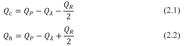
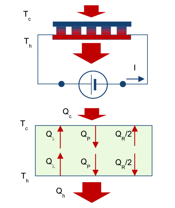
For comparison, let us give the equations of thermal balance (2.1) — (2.2) of thermoelectric module in cooling mode (Fig. 2.1).

Figure. 2.1 Heat flow diagram for cooling mode.

Generating mode


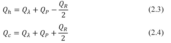
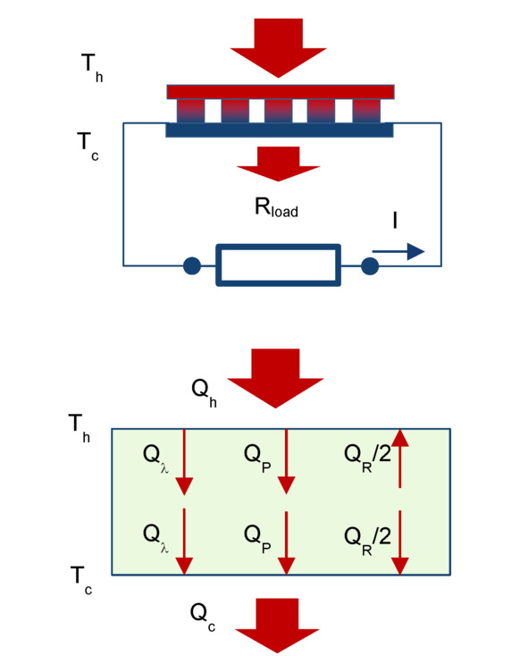
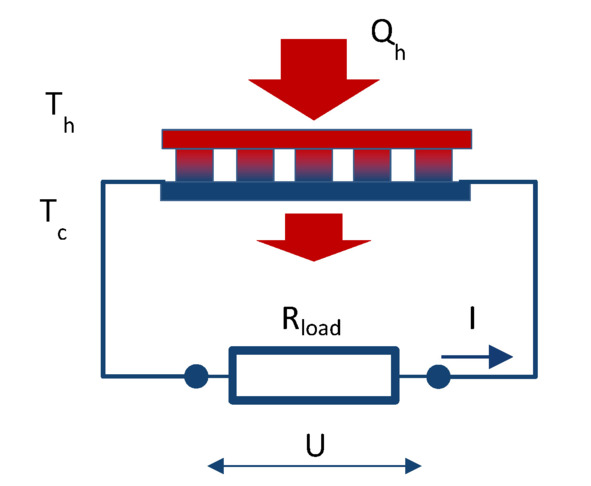
Heat balance equations of thermoelectric module in generating mode (Fig. 2.2) are the following.

where Qh — heat flow absorbed by the hot side of the module; Qc — heat flow emitted by the cold side of the module; Q λ — heat conducted due to thermal conductivity; QP — heat transferred due to the Peltier effect; QR  — Joule heat emitted due to the electric current in a closed circuit of the generator.
Figure. 2.2 Heat flow diagram for generating mode.

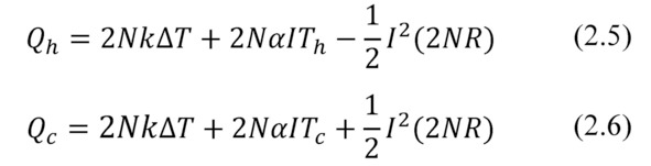
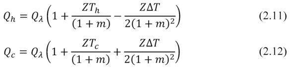
If to neglect temperature dependences of physical parameters, then heat balance equations in the generator mode can be written as the following:

where Th, Tc — temperatures of the hot and cold sides of generator module, respectively; N — number of pairs of thermoelements (pellets) in the module; α — average value of thermal motive force (thermoEMF), other words — Seebeck coefficient of pair of pellets n- and p- type; k -average heat conductivity of the pellet pair; Δ T — temperature difference (Δ T=Th-Tc) ; I — electric current through the module.

Here and below average values α, k, R are used — average values of paired thermoelements (pellets) of n-and p-type. For example, α= (αnp) /2. And these parameters refer to average operating temperature of pellets, in situations where the temperature dependency properties can generally be neglected.

Main parameters

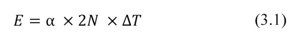
Thermoelectromotive force (ThermoEMF) E of a thermoelectric generator depends on the temperature difference ΔT, number of thermoelements N and Seebeck coefficient α as the following

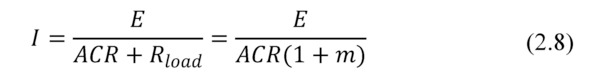
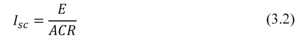
We introduce the notation for internal resistance of thermoelectric generator ACR=2NR, and for external load resistance — Rload.

Electric current through the generator is determined by thermoEMF E and total resistance of closed circuit (Fig. 2.2):

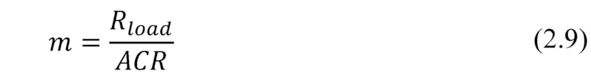
Here we introduce important parameter m — the ratio of the external load Rload to internal resistance of generator module ACR.

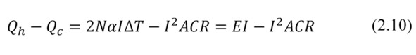
From the balanced equation (2.5) and (2.6) one can find that:

First member EI of the difference (2.10) is the total heat that is converted into electric current by the thermoelectric generator. The second member I2ACR is what part which comes back into heat due to the Joule effect.

— When the difference (2.10) is equally to zero (short circuit mode, external load resistance equal to zero) then all the converted energy comes back into heat.

— When the difference is positive (there is non-zero external load), i.e. the generator converts heat into electricity.

With given ratios (2.7) — (2.9) the balance equations (2.3) and (2.4) can be rewritten as the follows:

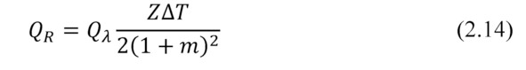
where Z — Figure-of-Merit of thermoelectric module; Qλ — heat flow due to thermal conductivity through the module (Qλ=2NkΔT).

Here the heat transferred through the Peltier effect QP

Joule heat Qλ

Voltage U in external circuit, taking into account (2.8), is the following.

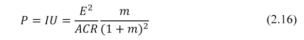
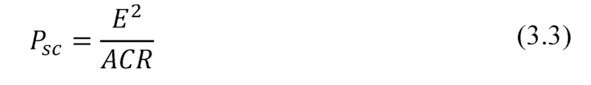
Power P in the external circuit (converted power).

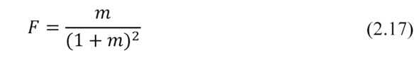
Here an important dimensionless factor F is appeared.

Formula (2.16) has a maximum defined by the dimensionless factor F, its dependence on the ratio m (2.9) of load resistance Rloadand internal resistance ACR of generator module (Fig. 2.3).

Figure 2.3 Dependence of dimensionless factor F from ratio m=Rload/ACR.

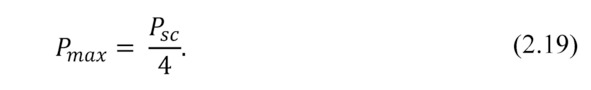
Maximum F and, respectively (2.16), maximum power P are achieved when m=1, i.e.

Important note — maximum power Pmax that can be obtained by a thermoelectric generator module is only one quarter of the power converted by the module in short circuit mode.

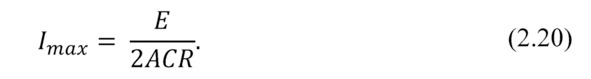
Electric current through the module in maximum power mode Imaxat m=1 is the following

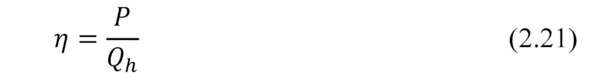
The thermoelectric generator efficiency η

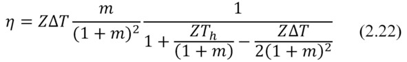
Taking into account formulas (2.7), (2.11) and (2.16) one can find that

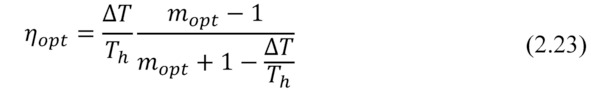
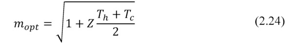
Investigating the formula for maximum at fixed temperature Thand Δ(Th, ΔT=const), we obtain formula for maximum efficiency η (optimal mode for efficiency):

Where the optimum ratio of load and internal resistances mopt (mopt=Rload/ACR) can be expressed as the following.

Note, please, the formula (2.24). If maximum power Pmax converted by generator can be achieved when m=1, then maximum efficiency η — at other value of this ratio — mopt (2.24). In the thermoelectric generator, as in any heat engine, maximum power mode operation differs from mode of maximum efficiency.

Effective thermal conductivity and thermal resistance

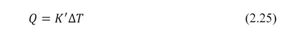
Heat Q passed through a media, which is the generator, one can write in general using the effective thermal conductivity K” of this media and temperature difference ΔT as the following.

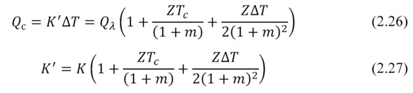
In working generator the heat is Qc (2.12), which differs from the heat transported due to “simple” thermal conductivity Qλ:

Effective thermal conductivity K” differs from conventional thermal conductivity K of agenerator due to the additional Peltier and Joule heat flows, that appear in the working generator, and which are superimposed on the conventional thermal conductivity (Fig. 2.2).

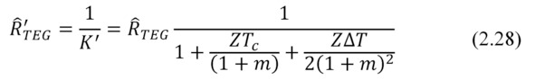
Thermal resistance of the working generator Ȓ’TEG is the following

To a first approximation, at small temperature differences ΔT the 3-rd member (Joule) in the sum in brackets (2.27) can be ignored. Indeed, it can be shown that contribution of this term at small temperature differences is small, no more than 0.5–1%.

Then

Exclusion of a member, depending on ΔT dramatically simplifies analysis of a thermoelectric generator in the tasks of complex ambient. Where the generator is placed between other media and interfaces with different thermal resistance, and it is desirable to optimize the thermal resistance Ȓ’TEG of the working generator (see Chapter 5).

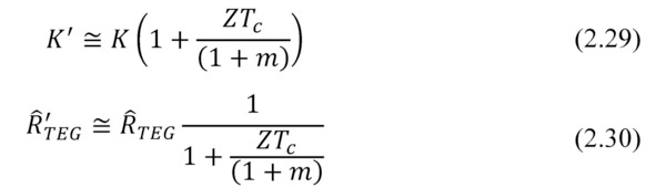
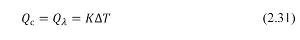
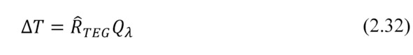
When open electrical circuit takes place in the generator, then there is no Peltier and no Joule heat flows. Only thermal conductivity heat flow takes place. In other words, then Rload=∞ and m=∞ then the formula (2.26) is simplified to:

Temperature difference ΔT at a generator module when an open circuit takes place is associated with heat flow of thermal contuctivity Qλ as the following.

Chapter 3. Optimization of electrical circuit

Preface. Thermoelectric generator transforms thermal energy and gives it to external electric circuit. Here coordination of elements of the electric circuit with parameters of the generator is essential for extraction of maximum power. In this Chapter questions of optimization of the electric circuit are considered.

Basic formulas

Simplified electrical circuit of a generator module is shown in Fig.3.1.

Figure. 3.1 Schematics of thermoelectric generator.

Maximum electric power transformed by a generator from heat source is defined by thermoEMF E and internal resistance ACR of the generator.

The thermoEMF E is found as the following

where α — thermoelectric coefficient (Seebeck coefficient) of pair of thermoelements n- and p-types; 2N — number of elements in generator module; Δ T -working temperature difference on generator module (Δ T=Th-Tc).

If to short the electric circuit of the generator (Rload=0), the short-circuit current Isc is

At short-circuit the power Psc allocated in the electric circuit is maximal.

However, all this power will be converted into Joule heat in thermoelements of the generator. In fact, heat converted into electric current returns again into the heat. There is no useful work.

A generator performs useful work when converted power is given out to the external load that has electrical resistance different from zero (Rload> 0).

...